
A4 Cabriolet Mk2
|
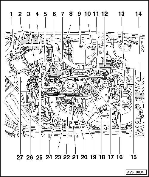
| 1 - | Air mass meter -G70- |
| q | → Fig. |
| q | Removing and installing → Chapter |
| 2 - | Fuel filter |
| q | Renewing → Rep. gr.20 |
| 3 - | Hall sender -G40- (camshaft position sensor) |
| q | Fitting location → Fig. |
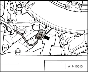
| 4 - | Coolant temperature sender -G62- |
| q | Removing and installing → Rep. gr.19 |
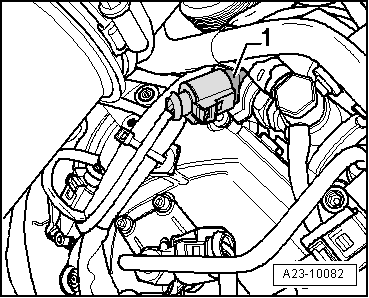
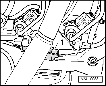
| 5 - | Fuel pressure regulating valve -N276- |
| q | Fitting location → Fig. „„Fuel pressure regulating valve -N276--1-““ |
| q | Removing and installing → Chapter |
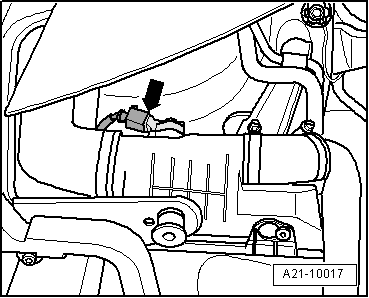
| 6 - | Connector for exhaust gas temperature sender 1 -G235- |
| 7 - | Intake manifold flap motor -V157- |
| q | Cylinder bank 1 |
| q | Removing and installing → Chapter |
| q | Intake manifold - exploded view → Chapter |
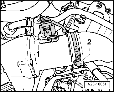
| 8 - | Control unit for turbocharger 1 -J724- |
| q | Removing and installing → Rep. gr.21 |
| 9 - | Exhaust gas temperature sender 1 -G235- |
| q | On turbocharger |
| q | Removing and installing → Rep. gr.26 |
| 10 - | Lambda probe -G39- with Lambda probe heater -Z19- |
| q | Removing and installing → Chapter |
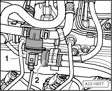
| 11 - | Exhaust gas recirculation cooler change-over valve -N345- |
| q | Fitting location → Fig. |
| q | Overview of exhaust gas recirculation system → Rep. gr.26 |
| 12 - | Intake manifold flap 2 motor -V275- |
| q | Cylinder bank 2 |
| q | Removing and installing → Chapter |
| q | Intake manifold - exploded view → Chapter |
| 13 - | Connector for Lambda probe -G39- |
| q | Fitting location → Fig. |
| 14 - | Throttle valve module -J338- |
| 15 - | Injectors (piezo injectors) |
| q | Cylinder bank 2 |
| q | Removing and installing → Chapter |
| 16 - | Fuel pressure sender -G247- |
| q | Removing and installing → Chapter |
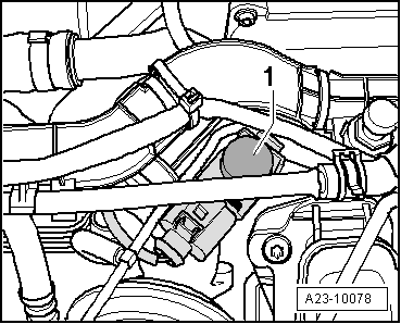
| 17 - | Vacuum unit |
| q | For change-over flap for exhaust gas recirculation cooler |
| 18 - | Mechanical exhaust gas recirculation valve |
| q | Overview of exhaust gas recirculation system → Rep. gr.26 |
| q | Removing and installing → Rep. gr.26 |
| 19 - | High-pressure fuel pump |
| q | With gear-type fuel system pressurisation pump |
| q | With fuel metering valve -N290- |
| q | High-pressure pump generates fuel pressure up to 1600 bar |
| q | Gear-type fuel system pressurisation pump generates fuel pressure between 4 and 5 bar |
| q | Exploded view: vehicles up to 09.2005 → Chapter; vehicles from 09.2005 onwards → Chapter |
| q | Removing and installing: vehicles up to 09.2005 → Chapter; vehicles from 09.2005 onwards → Chapter |
| 20 - | Fuel supply line connection |
| 21 - | Fuel return line connection |
| 22 - | Fuel metering valve -N290- |
| q | Do not unscrew |
| q | Screwed directly into high-pressure fuel pump |
| 23 - | Exhaust gas recirculation valve -N18- |
| q | Fitting location → Fig. |
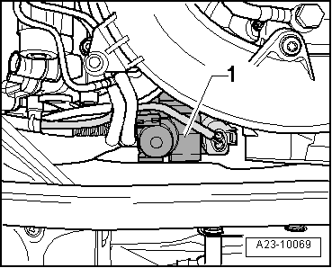
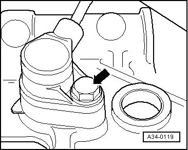
| 24 - | Oil pressure switch -F1- |
| q | → Fig. |
| q | Removing, installing and testing → Rep. gr.17 |
| 25 - | Fuel temperature sender -G81- |
| q | Fitting location → Fig. |
| 26 - | Pressure retention valve |
| q | → Fig. |
| q | In return lines from cylinder banks 1 and 2 |
| q | The pressure retention valve maintains a residual pressure of approx. 10 bar in the return lines. |
| q | This residual pressure is required for the control function of the piezo injectors. |
| q | The pressure retention valve may only be renewed together with the fuel return lines. |
| q | After replacement, engine must be run at idling speed for approx. 2 minutes to bleed fuel system |
| q | Checking pressure retention valve → Chapter |
| 27 - | Injectors (piezo injectors) |
| q | Cylinder bank 1 |
| q | Removing and installing → Chapter |
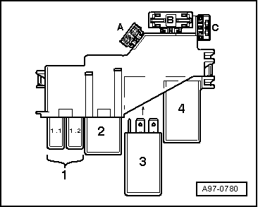
| A - | Electronics box in plenum chamber |
| q | Engine control unit -J623- with altitude sender |
| q | Removing and installing → Chapter |
| q | Fuel pump relay -J17- → Fig. |
| q | Starter inhibitor relay -J207- → Fig. |
| q | Terminal 30 voltage supply relay -J317- → Fig. |
| q | Automatic glow period control unit -J179- → Fig. |
| B - | Brake light switch -F- and brake pedal switch -F47- |
| q | In footwell on brake pedal |
| C - | Accelerator position sender -G79- and accelerator position sender 2 -G185- |
| q | In footwell on accelerator pedal |
| q | On vehicles with automatic gearbox the function of the kick-down switch must be re-adapted if this part is renewed. |
| q | Refer to Guided Fault Finding or → Rep. gr.20 for adapting kick-down function |
| D - | Charge pressure sender -G31- |
| q | With intake air temperature sender -G42- |
| q | In charge air cooler (left-side) → Fig. |
| q | Removing and installing → Rep. gr.21 |
| E - | Starter motor relay -J53- and starter motor relay 2 -J695- |
| q | For fitting location refer to → Current flow diagrams, Electrical fault finding and Fitting locations |
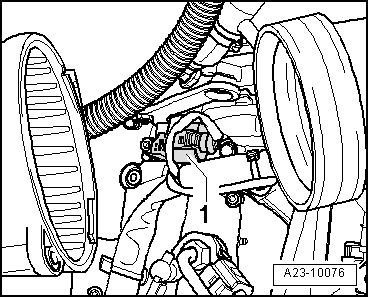
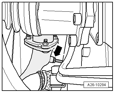
| F - | Engine speed sender -G28- |
| q | Fitting location → Fig. |
| G - | Low heat output relay -J359- and high heat output relay -J360- |
| q | Fitting location in 3-position relay carrier → Current flow diagrams, Electrical fault finding and Fitting locations |
| H - | Air filter bypass flap valve -N275- |
| q | These components (bypass flap with air filter bypass flap valve -N275-) are not installed on certain equipment versions or on vehicles for certain export markets |
| q | If fitted, the bypass flap is located in the air cleaner housing and the air cleaner bypass flap valve -N275- is located on the outside of the air cleaner housing |
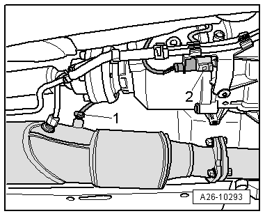
| I - | Exhaust gas temperature sender 2 for cylinder bank 1 -G448- |
| q | Only fitted on vehicles with particulate filter |
| q | Located downstream of starter catalytic converter |
| q | For fitting location refer to → Fig. |
| q | Removing and installing → Rep. gr.26 |
| J - | Temperature sender before particulate filter -G506- |
| q | Only fitted on vehicles with particulate filter |
| q | Located between main catalytic converter and particulate filter |
| q | For fitting location refer to → Fig. |
| q | Removing and installing → Rep. gr.26 |
| K - | Exhaust gas pressure sensor 1 -G450- |
| q | Only fitted on vehicles with particulate filter |
| q | Adaption must be performed after renewing this component |
| q | Removing and installing → Chapter |
| L - | Particulate filter |
| q | Fitted on vehicle underbody |
| q | Combined as one component with main catalytic converter (located upstream) |
| q | Adaption must be performed after renewing this component |
| q | Removing and installing → Rep. gr.26 |
|
|
|
|
|
|
|
|
|
|
|
|
|
|
|
|
|
|
|
|
|
|
|
|
|