audi Workshop Repair Guides

Audi Workshop Service and Repair Manuals

Servicing outer constant velocity joint > < Exploded view of components
Servicing inner constant velocity joint
   
Removing inner constant velocity joint
–  Clamp drive shaft in vice.
Use jaw protectors.
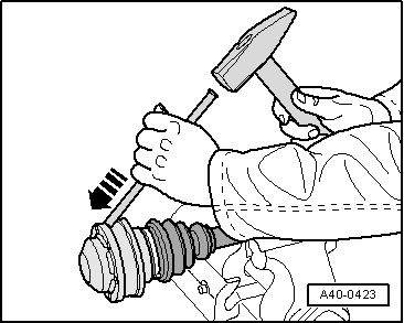
–  Drive off cover with a copper or brass drift.
  A40-0423
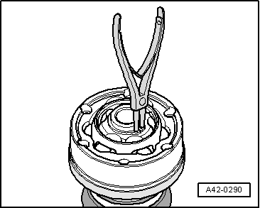
–  Remove circlip.
–  Remove drive shaft grease and mark installation position of constant velocity joint relative to drive shaft.
  A42-0290
–  Clamp constant velocity joint with drive shaft in vice, as shown in illustration.
–  A second person must hold the drive shaft horizontal to prevent the constant velocity joint from being damaged.
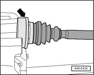
–  Open out rim - arrow - of cap slightly using a small chisel.
–  Drive off cap with a copper or brass drift.
  A40-0424
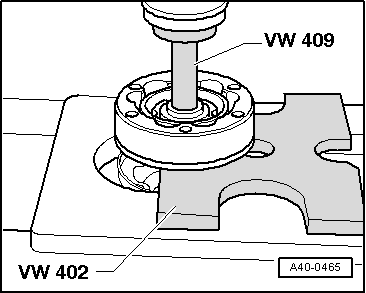
–  Press constant velocity joint off drive shaft.
–  Take off CV joint boot with cap.
  A40-0465
Installing inner constant velocity joint
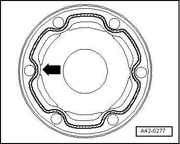
–  Apply sealant D 454 300 A2 on clean inner surface of cover → Item and cap on CV joint boot → Item (hatched area). Route continuous bead of sealant (2 ... 3 mm Ø) around inside of holes -arrow-.
Boot and contact surface of cap must be free of grease.
–  Push new boot with cap onto drive shaft.
–  Pack 85 g of drive shaft grease into boot.
  A42-0277
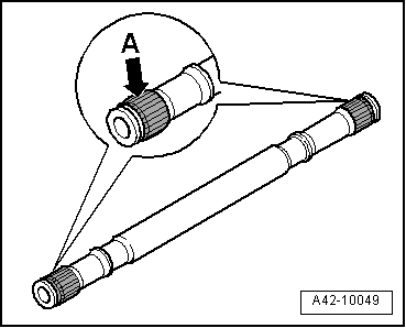
–  Grease splines -A- on drive shaft lightly with grease used in joint before fitting joint or triple roller spider onto drive shaft.
  A42-10049
–  Use adhesive tape or similar -arrow- to keep components of constant velocity joint together.
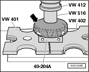
–  Press on constant velocity joint.
  Note
Chamfer on internal diameter of ball hub (splines) must face drive shaft.
Use the special tools shown in the illustration.
Special tool 40-204 A and the clamping surface on drive shaft must be free from grease.
–  Fit circlip.
–  Press 35 g of drive shaft grease through the ball raceways into the joint.
  A40-0466
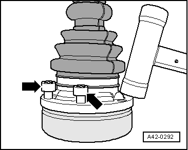
–  Using bolts -arrows-, align CV joint boot with cap in relation to bolt holes.
The alignment must be very accurate, because no further alignment is possible once the part has been hammered on.
–  Drive on CV joint boot with cap using a plastic hammer.
–  Remove surplus sealant immediately as it is pressed out.
  A42-0292
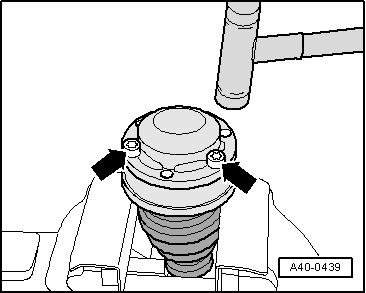
–  Using bolts -arrows-, align new cover in relation to bolt holes.
The alignment must be very accurate, because no further alignment is possible once the part has been hammered on.
–  Drive on cover using a plastic hammer.
–  Remove surplus sealant immediately as it is pressed out.
  A40-0439

Servicing outer constant velocity joint > < Exploded view of components