
A4 Cabriolet Mk2
| Part IV: Hub carrier - front-wheel drive |
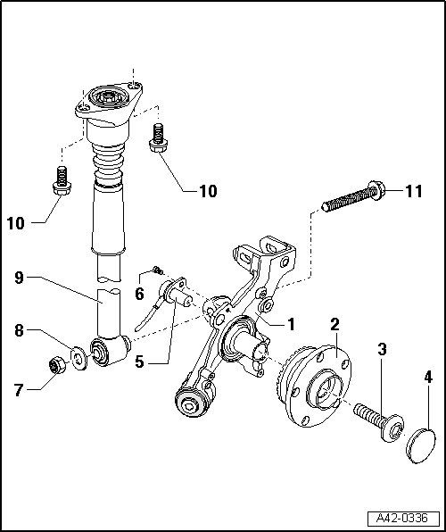
| 1 - | Hub carrier |
| q | Vehicles with front-wheel drive |
| q | Removing and installing → Chapter |
| q | Servicing → Chapter |
| 2 - | Wheel bearing unit |
| q | Removing and installing → Chapter |
| q | Wheel bearing and wheel hub are combined in one housing. |
| q | This wheel bearing/hub unit is maintenance-free and has zero play. There is no provision for adjustment or repair. |
| q | Does not always have to be renewed |
| q | Wheel bearing unit is OK and does not have to be renewed if it can be pulled off hub carrier by hand. |
| q | Wheel bearing unit must be renewed if it cannot be pulled off by hand |
| q | Renew only as complete unit |
| 3 - | Flange bolt |
| q | Always renew |
| q | 200 Nm + 180° |
| q | Tighten to 200 Nm while vehicle is raised; turn through specified angle only when vehicle is standing on its wheels |
| q | Do not loosen more than 90° when vehicle is standing on its wheels |
| 4 - | Grease cap |
| q | Always renew if removed |
| q | Proper sealing can only be achieved by installing a new grease cap. |
| q | This is essential for optimum function and service life. |
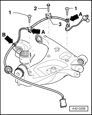
| 5 - | Speed sensor |
| q | Routing of wiring → Fig. |
| 6 - | Hexagon socket head bolt |
| q | 10 Nm |
| 7 - | Self-locking nut |
| q | Always renew |
| 8 - | Washer |
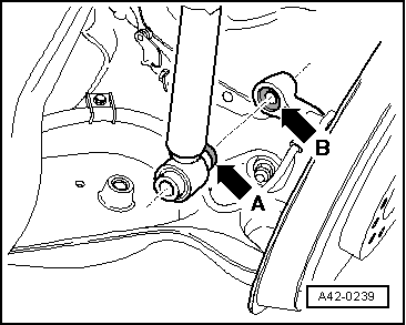
| 9 - | Shock absorber |
| q | Discharging and charging system on vehicles with Dynamic Ride Control (DRC II) → Chapter |
| q | Removing and installing → Chapter |
| q | Note correct installation position → Fig. |
| q | Note different running gear versions; see vehicle data sticker → Anchor |
| q | Defective shock absorbers must always be degassed and drained before disposal → Chapter |
| q | Checking shock absorber following removal → Chapter |
| 10 - | Bolt with washer |
| q | 36 Nm |
| 11 - | Bolt with washer |
| q | 150 Nm + 90° |
| q | Always renew |
| q | Suspension must be in unladen position when tightening bolt connections |
|
|