audi Workshop Repair Guides

Audi Workshop Service and Repair Manuals

Assembly mountings - exploded view > < Removing and installing subframe
Renewing subframe bushes
Special tools and workshop equipment required
   
t  Engine and gearbox jack -V.A.G 1383 A- with universal gearbox support -V.A.G 1359/2-
t  Torque wrench -V.A.G 1331-
t  Torque wrench -V.A.G 1332-
  W00-0120
t  Foot pump with high-pressure hose -V.A.G 1389 A/1-
If there is a hand pump -V.A.G 1389/1- available in the dealership it can be converted to a foot-operated pump.
To do this, use the conversion set -V.A.G 1389/4-.
Special tools and workshop equipment required
  W00-0681
t  Hydraulic wheel bearing tool -V.A.G 1459 B-
t  Hollow piston cylinder HKZ-15 -mit Druckstück E-0-204-T hydraulisch-
t  Pull rod -E-0-217+218-
t  Special nut -E-8-214-
t  Thrust piece -E-5-
t  Assembly tool -T40033/1-
t  Support ring -T40033/2-
t  Tube -T40033/3-
t  Support -T40033/4-
t  Assembly tool -T40033/5-
t  Support -T40033/6-
t  Spindle -T40034-
t  Nut -T40034/1-
t  Nut -T40034/2-
  Note
t  The same special tools and workshop equipment can be used for renewing the subframe bushes on vehicles with front-wheel drive and vehicles with four-wheel drive.
t  The subframe bushes are hydro-bushes, not conventional bonded rubber bushes → Parts catalogue
t  The bushes can only be removed and installed with the subframe lowered.
t  Mark position of bushes in relation to subframe before removing.
  W00-0676
Removing front/rear hydro-bushes
–  Remove wheels.
–  Remove coil springs (left and right) → Chapter.
–  Only if front hydro-bush is being renewed: remove rear underbody trim (left/right).
1 - Underbody trim (left-side)
  A42-0331
–  If fitted, remove diagonal struts -1- and -2- → Chapter.
Only for rear hydro-bushes
–  Remove anti-roll bar → Chapter.
  A42-0330
Front and rear hydro-bushes (continued)
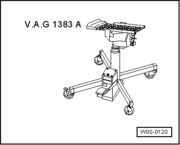
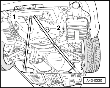
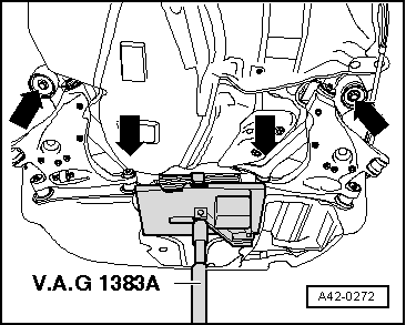
–  Apply engine/gearbox jack -V.A.G 1383 A- with universal gearbox support -V.A.G 1359/2- and a suitable wooden block to subframe/final drive (illustration shows vehicle with front-wheel drive).
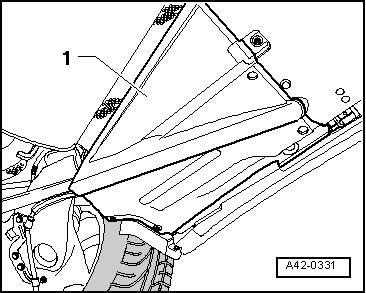
–  Wind strap around subframe/final drive.
  Note
t  If a front hydro-bush is being renewed, loosen only the front subframe bolts.
t  If a rear hydro-bush is being renewed, loosen only the rear subframe bolts.
t  If a further subframe bolt is loosened (front or rear), wheel alignment must be performed following installation.
–  Loosen front or rear subframe bolts.
–  Carefully lower subframe approx 5 cm.
–  Only remove those subframe bolts where the hydro-bush is to be renewed.
  A42-0272
–  Using felt pen or similar, mark position of hydro-bush -1- in relation to subframe -2- (illustration shows subframe of a front-wheel drive vehicle).
Arrow A: direction of travel
Arrows B and C: markings
  A42-0332
–  Apply special tools as shown in illustration.
1 - Nut -T40034/1- or -T40034/2-
2 - Assembly tool -T40033/1-
3 - Support ring -T40033/2-
4 - Tube -T40033/3-
5 - Support -T40033/4-
6 - Hollow piston cylinder -HKZ-15-
7 - Thrust piece -E-5-
8 - Special nut -E-8-214-
9 - Spindle -T40034-
10 - Subframe
–  Take up play in special tools.
–  Extract hydro-bush by actuating pump.
  Note
When pulling out the hydro-bush using hydraulic wheel bearing tool -V.A.G 1459 B-, the tool must be repositioned for removal.
Installing front/rear hydro-bushes
Front and rear hydro-bushes are different. Ensure correct parts are used when installing. → Parts catalogue
The hydro-bush must be installed facing in the correct direction, note the marks on the subframe for this purpose.
  A42-0333
–  Set up special tools with hydro-bush on subframe as illustrated
Ensure correct position when attaching support -T40033/6-.
1 - Nut -T40034/1- or - T40034/2-
2 - Support -T40033/6-
3 - Hydro-bush
4 - Assembly tool -T40033/5-
5 - Hollow piston cylinder -HKZ-15-
6 - Thrust piece -E-5-
7 - Special nut -E-8-214-
8 - Spindle -T40034-
9 - Subframe
–  Take up play in special tools with hydro-bush.
–  Apply assembly lubricant G 294 421 A1 diluted with water (ratio 1:100) all round hydro-bush.
  A42-0334
–  Ensure that the ends of the rubber beads of the hydro-bush -1- line up with the markings -arrows B and C- on the subframe -2-.
-Arrow A- direction of travel
–  Press in hydro-bush as far as stop by actuating pump.
  Note
t  When pulling in the hydro-bush using special tool -V.A.G 1459 B-, the tool must be repositioned during installation.
t  Ensure that the hydro-bush remains straight during the first stage of installation, otherwise the outer ring may be damaged.
–  Lift subframe with engine and gearbox jack -V.A.G 1383 A-.
–  Install and tighten new subframe bolts with new washers → Item and → Item (front-wheel drive), or → Item and → Item (four-wheel drive).
Rear hydro-bushes only:
–  Install anti-roll bar → Chapter.
Front and rear hydro-bushes (continued)
  A42-0332
–  If fitted, install diagonal struts -1- and -2- → Chapter.
–  Install underbody trim (left and right).
–  Install coil springs (left and right) → Chapter.
–  Fit and secure wheel → Wheels and tyres; Rep. Gr.44.
–  Check wheel alignment if more than 2 bolts for hydro-bushes have been loosened → Chapter.
Wheel alignment must always be checked and adjusted if necessary using VW/Audi-approved equipment.
  A42-0330

Assembly mountings - exploded view > < Removing and installing subframe