audi Workshop Repair Guides

Audi Workshop Service and Repair Manuals

Aerials in rear lid > < Connectors and pin assignment
Navigation operating electronics control unitJ402
   
Navigation operating electronics control unit -J402-
1 - Multi-pin connector, 32-pin (not used)
2 - GPS connection (blue) from navigation system aerial -R50-
3 - Connection block with four multi-pin connectors and one fuse for unit
4 - Connection, ZF (white) to left aerial module -R108-
5 - Connection HF (white) from left aerial module -R108-

  Note
Contacts which are not listed are not used.
   
1 - Multi-pin connector, 32-pin (not used)
  A91-0983
A - Multi-pin connector, 8-pin, brown (T8q)
2 - Loudspeaker (+) (front right) (not with BOSE)
3 - Loudspeaker (+) (front left) (not with BOSE)
6 - Loudspeaker (-) (front right) (not with BOSE)
7 - Loudspeaker (-) (front left) (not with BOSE)
  A91-0947
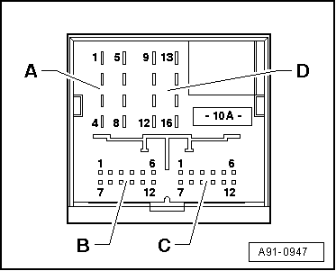
B - Multi-pin connector, 12-pin, blue (T12n)
2 - CD earth to CD changer -R41- / iPod holder -R192- / satellite radio -R146-
3 - Speed signal (not used)
4 - Permanent live to CD changer -R41- / iPod holder -R192-
5 - L-diagnosis
6 - CD data output to CD changer -R41- / iPod holder -R192-
7 - BOSE coding to earth (only with BOSE)
8 - Signal (left-side) from CD changer -R41- / iPod holder -R192- / satellite radio -R146-
9 - Signal (right-side) from CD changer -R41- / iPod holder -R192- / satellite radio -R146-
10 - Switched positive to CD changer -R41- / iPod holder -R192-
11 - CD data input from CD changer -R41- / iPod holder -R192-
12 - CD-CLK from CD changer -R41- / iPod holder -R192-
  A91-0947
C - Multi-pin connector, 12-pin, green (T12m)
1 - Microphone input (–) from telephone microphone -R38- (from MY 06)
2 - Signal from reversing light switch -F4- (not used)
3 - Signal (front left) to amplifier -R12- (only with BOSE)
4 - Microphone output (–) to telephone transmitter and receiver unit -R36- (from MY 06)
5 - Signal (rear left) to amplifier -R12-
6 - NF– (low frequency) from telephone transmitter and receiver unit -R36-
7 - Microphone input (+) from telephone microphone -R38- (from MY 06)
8 - Signal earth to amplifier -R12-
9 - Signal (front right) to amplifier -R12- (only with BOSE)
10 - Microphone output (+) to telephone transmitter and receiver unit -R36- (from MY 06)
11 - Signal (rear right) to amplifier -R12-
12 - NF+ (low frequency) from telephone transmitter and receiver unit -R36-
  A91-0947
D - Multi-pin connector, 8-pin, black (T16j)
9 - CAN Bus High (Infotainment)
10 - CAN Bus Low (Infotainment)
11 - NF mute (low frequency) (not used)
12 - Terminal 31
13 - Switched positive to amplifier -R12-
14 - Anti-theft alarm earth from convenience system central control unit -J393-
15 - Terminal 30
16 - Permanent live
  A91-0947

Aerials in rear lid > < Connectors and pin assignment