audi Workshop Repair Guides

Audi Workshop Service and Repair Manuals

Removing and installing bracket for hydraulic unit > < Anti-lock brake system (ABS) Bosch 5.0
Brake System
Anti-lock brake system (ABS) Bosch 5.0
Hydraulic unit and brake pipes
 
A45-0023

The tightening torque for all brake pipes on the Audi A4 is 15 Nm.

  • Brake master cylinder and brake servo
  • Brake pipe
    • ◆ Brake master cylinder/floating piston circuit to hydraulic unit
    • ◆ Screw connection at brake master cylinder: M12x1
    • ◆ Screw connection at hydraulic unit: M12x1
  • Brake pipe
    • ◆ Brake master cylinder/push rod piston circuit to hydraulic unit
    • ◆ Screw connection at brake master cylinder: M12x1
    • ◆ Screw connection at hydraulic unit: M12x1
 
A45-0023
  • Grommet
  • Connector, ABS wiring harness
    • ◆ Release and detach
    • ◆ The connector is part of the ABS wiring harness. Note that there are different versions for FWD and 4WD models.
    • ◆ Ensure correct positioning
  • Bolt, 5 Nm
  • Cover
  • Relay for solenoid valves
  • Relay for return pump
  • ABS hydraulic unit
    • ◆ Note that there are different versions:
    • ‒ ABS FWD models
    • ‒ ABS/EDL FWD models, ABS/EDL/TCS FWD models => Fig.1
    • ‒ ABS/EDL 4WD models => Fig.2
    • ‒ ABS/EDL 4WD models 05.95 ▸=>Fig.3
 
A45-0023
    • ◆ No repair work may be carried out on the hydraulic unit, with the exception of replacing both relays . Never unfasten bolted joints
    • ◆ If necessary, replace hydraulic unit only as a complete assembly.
    • ◆ Replacement hydraulic units are supplied pre-bled
    • ◆ Removing and installing the hydraulic unit
    • ‒ Disconnect earthing strap from battery.
    • ‒ Seal the brake lines and connections immediately with dummy plugs.
 
A45-0023
    • ‒ When replacing the hydraulic unit, the new hydraulic unit must be bolted into the bracket-item13 -. The dummy plugs must be removed from the brake line connections. The brake lines should be connected in accordance with the designations on the hydraulic unit.
    • ‒ The tightening torque of the brake pipes is 15 Nm.
    • ‒ Bleed brake system
    • ‒ Carry out high- and low-pressure test => Page 45-4
    • ‒ Perform electrical test

=> Running Gear Self-Diagnosis; Repair group 01

 
A45-0023
  • Cheese-head bolt, 15 Nm
  • Washer
  • Bracket for hydraulic unit
    • ◆ Removing and installing bracket => Page 45-23
  • Combi bolt, 8 Nm
  • Toothed lock washer
  • Earth wire
    • ◆ Ensure good contact
  • Hexagon nut, 10 Nm
 
A45-0023
  • Brake pipe
    • ◆ Hydraulic unit to front right brake caliper
  • Brake pipe
    • ◆ Hydraulic unit to front left brake caliper
  • Brake pipe
    • ◆ Hydraulic unit to rear right brake caliper
  • Brake pipe
    • ◆ Hydraulic unit to rear left brake caliper
 
A45-0022

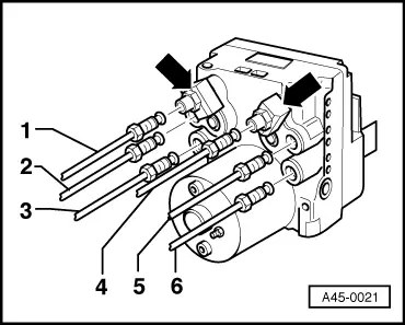
→ Fig.1    Hydraulic unit for ABS/EDL FWD models and also for ABS/EDL/TCS FWD models: brake pipe connections 15 Nm

  •     1 -    Hydraulic unit - brake master cylinder (push rod piston circuit)
  •     2 -    Hydraulic unit - rear right brake caliper
  •     3 -    Hydraulic unit - front left brake caliper
  •     4 -    Hydraulic unit - brake master cylinder (floating piston circuit)
  •     5 -    Hydraulic unit - rear left brake caliper
  •     6 -    Hydraulic unit - front right brake caliper

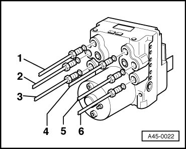
Note:

The pressure dampers are not fitted to vehicles with 4WD and EDL suction control (05.95 onwards) => Fig.2

EDL suction control minimises control noises.

The working range of the pressure limiting valve in the hydraulic unit is raised from 90±25 bar to 170±25 bar.

 
A45-0021

→ Fig.2    Brake pipe connections at hydraulic unit

For models with 4WD and ABS/EDL- pressure control (up to 05 95):

Two pressure dampers are screwed into the hydraulic unit -arrows- on vehicles with 4WD and EDL pressure control.

The dampers are designed to smooth pressure peaks in the brake pipes and reduce control noises.

Counterhold at the hexagon of the pressure dampers when unfastening the brake pipes.

  •     1 -    Hydraulic unit - brake master cylinder (push rod piston circuit)
  •     2 -    Hydraulic unit - rear right brake caliper
  •     3 -    Hydraulic unit - front left brake caliper
  •     4 -    Hydraulic unit - brake master cylinder (floating piston circuit)
  •     5 -    Hydraulic unit - rear left brake caliper
  •     6 -    Hydraulic unit - front right brake caliper
 
A45-0022

→ Fig.3    Hydraulic unit for ABS/EDL - 4WD, suction control.

    • ‒ The EDL suction control was introduced on models with 4WD with effect from 05.95. This technology reduces the operating noise during an EDL control cycle.
    • ‒ The pressure dampers that were previously screwed into the hydraulic unit and were used to reduce the operating noise are no longer fitted. The working range of the pressure limiting valve in the hydraulic unit is raised from 90±25 bar to 170±25 bar.
    • ‒ Connector coding eliminates the risk of incorrectly connecting the hydraulic unit.
  •     1 -    Brake pipe 15 Nm
    • ‒ Extended version in line with FWD as the pressure damper screwed into the hydraulic unit is no longer fitted.
  •     4 -    Brake pipe 15 Nm
    • ‒ Extended version in line with FWD as the pressure damper screwed into the hydraulic unit is no longer fitted.

Removing and installing bracket for hydraulic unit > < Anti-lock brake system (ABS) Bosch 5.0