audi Workshop Repair Guides

Audi Workshop Service and Repair Manuals

Checking gear oil level in rear final drive > < Measuring and marking radial run-out at propshaft flange
5-Speed Manual Gearbox 01A (4WD)
Servicing prop shaft
Adjusting propshaft

Special tools, testers and auxiliary equipment required

  • ◆ Assembly tool 3298
  • ‒ Observe notes.

Adjustments must be carried out with the greatest care and attention since a poorly adjusted propshaft is often the cause of vibration and humming.

  • ‒ Remove cross member, if fitted, underneath exhaust system.
  • ‒ Remove rear section of exhaust system as from clamp(s):

=> 4-cylinder Engine (5-valve), Mechanical Components; Repair Group 26; Removing and installing exhaust system parts

=> 4-cylinder Engine (5-valve turbo), Mechanics; Repair Group 26; Removing and installing parts of exhaust system

=> 4-cylinder Diesel Direct Injection Engine (TDI), Mechanics; Repair Group 26; Removing and installing exhaust system

=> 6-cylinder Engine (2-valve), Mechanics; Repair Group 26; Removing and installing exhaust system

=> 6-cylinder Engine (5-valve), Mechanical Components; Repair Group 26; Removing and installing exhaust system parts

  • ‒ Remove heat shield above propshaft.
 
A39-0021
  • ‒ → Cut out the assembly device 3298, as illustrated in Fig.
  • ‒ Loosen securing bolts of centre propshaft mounting slightly.

 
V39-1728
  • ‒ → Engage assembly device 3298 and tighten plastic nuts.

Note:

Never fit assembly appliance onto balance plates.

  • ‒ Remove securing bolts and shims from centre mounting.
 
V39-1731
  • ‒ → Align centre propshaft mounting so that the dimension -a- on left-hand side is the same as dimension -a- on right-hand side.
  • ‒ Measure the distances -a-.
  • ‒ Select required shims from table. Part numbers

=> Parts List

The following shims are available

Distance -a-
(mm)

Shim thickness
(mm)

0 ... 3.0

-

3.1 ... 5.0

2

5.1 ... 7.0

4

7.1 ... 9.0

6

9.1 ... 11.0

8

11.1 ... 13.0

10

  • ‒ Install correct shims on left and right.

Aligning propshaft longitudinally

 
V39-1732
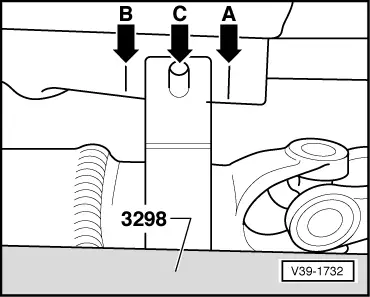
  • ‒ → Slide propshaft with assembly device to rear onto stop.
  • ‒ Mark position of centre mounting on body -arrow A-.
  • ‒ Push the propshaft with the assembly device forward as far as it will go.
  • ‒ Mark position of centre mounting on body -arrow B-.
  • ‒ Align propshaft -arrow C-.
    • ‒ The centre mounting must be positioned centrally between the markings -A- and -B-
  • ‒ Install securing bolts of propshaft centre mounting and previously determined shims and tighten.
  • ‒ Remove assembly device.
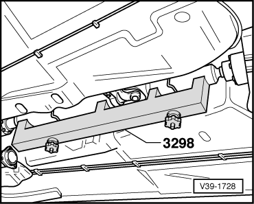
  • ‒ Install heat shield above propshaft.

The remaining installation steps are carried out in the reverse sequence - note the following points:

  • ‒ Stress free alignment of exhaust system

=> 4-cylinder Engine (5-valve), Mechanics; Repair Group 26; Removing and installing exhaust system parts, Stress-free alignment of exhaust system

=> 4-cylinder Engine (5-valve turbo), Mechanics; Repair Group 26; Removing and installing exhaust system parts, Stress-free alignment of exhaust system

=> 4-cylinder Diesel Direct Injection Engine (TDI), Mechanics; Repair Group 26; Removing and installing exhaust system

=> 6-cylinder Engine (2-valve), Mechanics; Repair Group 26; Removing and installing exhaust system

=> 6-cylinder Engine (5-valve), Mechanics; Repair Group 26; Removing and installing exhaust system parts, Stress-free alignment of exhaust system

Tightening torques

Component

Nm

Propshaft centre mounting to body

23

Cross member to body

25

Nuts for clamp

40

Checking gear oil level in rear final drive > < Measuring and marking radial run-out at propshaft flange