audi Workshop Repair Guides

Audi Workshop Service and Repair Manuals

Adjusting crown wheel > < Position of shims
5 & 6-Speed manual gearbox 01E, Front-wheel drive
Adjusting drive pinion

Repairs after which the drive pinion must be adjusted => table on Page 39-28.

Determining total shim thickness "Stotal" for shims "S3" + "S4"

(Setting preload of taper roller bearings for drive pinion)

  • ● Differential removed
  • ‒ Insert outer race for taper roller bearing for drive pinion into gearbox housing without shims => Fig.35-21.
 
V35-0987
  • ‒ → Insert outer race for taper roller bearing for drive pinion with shim "S4*" (1.0 mm thick) into bearing plate.

Note:

For measurement purposes a shim "S4" of 1.0 mm is initially inserted which is designated "S4*" After determining measurement "e" "S4*" will be replaced by the correct shim "S4".

  • ‒ Insert completely assembled drive pinion in gearbox housing.
  • ‒ Fit bearing plate with dowel sleeves and tighten to 25 Nm.
  • ‒ Rotate drive pinion 5 turns in each direction so that the bearing settles.
 
V39-1712
  • ‒ → Assemble measuring equipment, use a 30 mm dial gauge extension.
  • ‒ Set dial gauge (3 mm measuring range) to "0" with 2 mm preload.

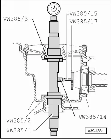
Note:

The tip of the dial gauge must be positioned on centre of drive pinion.

  • ‒ Lift drive pinion, without turning, and read off play on dial gauge.
    • ‒ Measurement in example: 0.90 mm

Note:

If the measuring procedure needs to be repeated, the drive pinion must first be rotated 5 turns in each direction again so that the taper roller bearing settles. Reset the dial gauge to "0" with 2 mm preload.

Formula:

"Stotal"

=

"S4*" + measurement + bearing preload

Example:

Inserted shim "S4*"

1.00 mm

+

Measured value (example)

0.90 mm

+

Bearing preload (constant)

0.15 mm

=

Total shim thickness "Stotal"
for "S3" + "S4"


2.05 mm

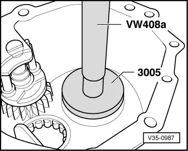
Determining thickness of shim "S3*"

Formula:

"S3*"

=

"Stotal" - "S4*"

Example:


Total shim thickness "Stotal"
for "S3" + "S4"


2.05 mm

-

Inserted shim "S4*"

1.00 mm

=

Thickness of shim "S3*"

1.05 mm

  • ‒ Remove outer race for taper roller bearing, insert shim "S3*" into gearbox housing and install outer race again => Fig.35-21.
  • ‒ Insert completely assembled drive pinion into gearbox housing again.
  • ‒ Fit bearing plate with dowel sleeves and tighten securing bolts to 25 Nm.
  • ‒ Rotate drive pinion 5 turns in each direction so that the bearing settles.

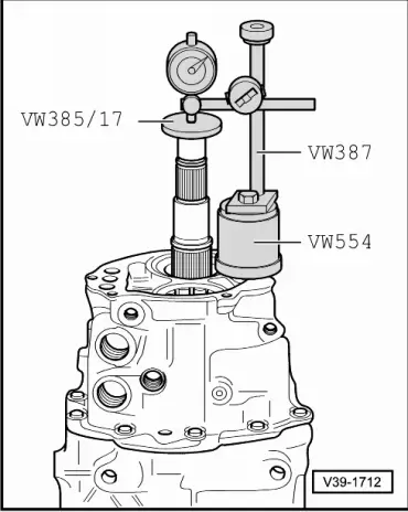
Determining measurement "e"

 
V39-0822

Note:

Measurement "e" is required to determine the final shim thickness of "S3" and "S4".

  • ‒ → Set adjustment rings of universal mandrel VW 385/1 to the following measurements:
    • ‒ Dimension a = 65 mm
    • ‒ Dimension b = 65 mm

 
V39-1158
  • ‒ → Assemble universal mandrel VW 385/1 as illustrated:
    • ‒ Dial gauge extension VW 385/15, 9.3 mm long
    • ‒ Master gauge VW 385/30
  • ‒ Set master gauge VW 385/30 to Ro = 59.65 mm and fit onto mandrel.
  • ‒ Set dial gauge (3 mm measuring range) to "0" with 2 mm preload.

Note:

The gauge VW 385/27 can also be used in place of the master gauge VW 385/30 (Ro = 59.65 mm).

 
V39-1881

→ Arrangement of measuring equipment when determining dimension "e"

  • ‒ Place end measuring plate VW 385/17 onto drive pinion head.

Note:

Ensure plate contact surface fits exactly and is free of oil.

  • ‒ Take master gauge off mandrel.
  • ‒ Insert mandrel into gearbox housing.
    • ‒ The centring disc 385/3 faces towards cover for final drive
  • ‒ Fit cover for final drive and tighten 4 bolts to 25 Nm.
  • ‒ Using the adjustable ring, pull 2nd centring disc VW 385/2 out as far as possible so that the mandrel can still just be turned by hand.
 
V39-1716
  • ‒ → Turn mandrel until the dial gauge plunger tip touches the end measuring plate on drive pinion head, then measure maximum deflection (return point).
    • ‒ Measurement in following example: "e" = 0.16 mm (in red scale)

Determining thickness of shim "S3"

Formula:

"S3"

=

"S3*" + "r" + "e"

("e" in black scale)

or

"S3"

=

"S3*" + "r" - "e"

("e" in red scale)

Notes:

  • ◆ The deviation "r" related to the master gauge "Ro" is measured for the final drive sets supplied as replacement parts and inscribed on outer circumference of crown wheel.
  • ◆ If measurements are obtained on red scale then subtract value "e".
  • ◆ If measurements are obtained on black scale then add value "e".

Example:

Inserted shim "S3*"

1.05 mm

+

Deviation "r"

0.38 mm

-

Determined "e"
(in red scale)


0.16 mm

=

Thickness of shim "S3"

1.27 mm

  • ‒ Determine shim(s) from table. Part numbers

=> Parts catalogue

The following shims are available for "S3"

Shim thickness (mm) 1)

0.45

0.60

0.75

0.50

0.65

0.55

0.70

    1)    Using the shim tolerance variations it is possible to find the exact shim thickness required, insert two shims if necessary.

Determining thickness of shim "S4"

Formula:

"S4"

=

"Stotal" - "S3"

Example:


Total shim thickness "Stotal"
for "S3" + "S4"


2.05 mm

-

Thickness of shim "S3"

1.27 mm

=

Thickness of shim "S4"

0.78 mm

  • ‒ Determine shim(s) from table. Part numbers

=> Parts catalogue

The following shims are available for "S4"

Shim thickness (mm) 1)

0.45

0.65

0.85

0.50

0.70

0.90

0.55

0.75

0.60

0.80

    1)    Using the shim tolerance variations it is possible to find the exact shim thickness required, insert two shims if necessary.

Performing check measurement

Checking dimension "r"

 
V39-1716
  • ‒ Install drive pinion with determined shims "S3" and "S4" and turn 5 turns in both directions.
  • ‒ → Insert universal mandrel, => "determining measurement 'e'" on Page 39-34 and perform check measurement.
  • ‒ Read off dial gauge anti-clockwise (red scale).
    • ‒ If the shims have been correctly selected, the deviation "r" (marked on outer circumference of crown wheel) must be shown - within a tolerance of ± 0.04 mm

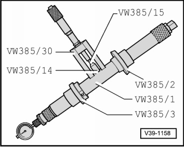
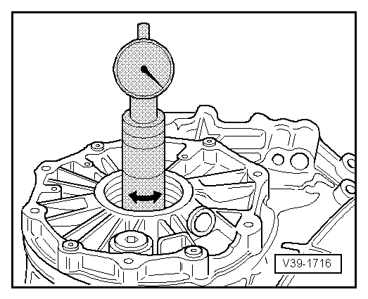
Note:

Then, (after removing universal mandrel) check again that the dial gauge, with master gauge VW 385/30 in place, indicates "0" with 2 mm preload, otherwise correct adjustments.

Measuring friction torque (check)

Notes:

  • ◆ The taper roller bearings for the drive pinion are low-friction bearings, which means that the friction torque is only of limited use for checking the adjustment. The only way to make the adjustment accurately is by calculating the total shim thickness "Stotal".
  • ◆ Do not additionally oil new tapered roller bearing to perform the friction torque measurement. These bearings have already been treated with a special oil by the manufacturer.
 
V39-1718
  • ‒ → Fit torque gauge 0 ... 600 Ncm -A- onto drive pinion.

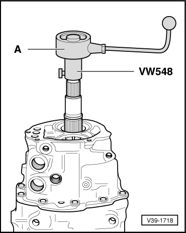
Friction torque specification:

New bearings

Used bearings

80 ... 150 Ncm

30 ... 60 Ncm

Adjusting crown wheel > < Position of shims