audi Workshop Repair Guides

Audi Workshop Service and Repair Manuals

Checking oil level in gearbox > < Checking gear stick setting
5 & 6-Speed manual gearbox 01E, Front-wheel drive
Removing and installing gearbox

Special tools, testers and auxiliary items required:

  • ◆ Gearbox support 3282
  • ◆ Adjustment plate 3282/12
  • ◆ Gearbox jack V.A.G 1383 A

Removing

  • ‒ Obtain radio code on vehicles with coded radio.
 
A10-0202
  • ‒ With ignition switched off disconnect battery earth strap.

Note:

For better access to the bolts securing the engine to the gearbox, remove the exhaust pipe and catalytic converter first.

  • ‒ → Unbolt noise insulation cover above cylinder head cover -arrows-.
 
A34-0135
  • ‒ → Remove heat shield above turbocharger -arrows-.

 
A10-0206
  • ‒ → Unbolt exhaust pipe from turbocharger manifold -arrows-.
 
N02-0130
  • ‒ → Remove noise insulation (two sections, -arrows A ... C-).
  • ‒ Unbolt mounting for noise insulation.

 
A34-0180
  • ‒ Unscrew bolts -arrows- for bracket -A-.
 
A34-0136
  • ‒ → Remove support -1-.
  • ‒ Loosen clamp on exhaust pipe -arrows on left- and take out exhaust pipe together with catalytic converter.

 
A34-0116
  • ‒ Remove engine/gearbox securing bolts which are accessible from above.
  • ‒ → Slacken bolt -A- (on rear of turbocharger) by a few turns and pivot strut -B- to one side in direction of arrow. Then tighten bolt -A- again slightly.

Note:

The illustration shows the engine from the rear with the gearbox removed.

 
A34-0137
  • ‒ → Slacken bolt -2- on noise insulation cover above left-hand drive shaft.
  • ‒ Disengage retainer -1- and remove noise insulation cover.

 
A34-0138
  • ‒ → Remove heat shield for left-hand inner joint -1- from gearbox
    -arrows-.
  • ‒ Unbolt drive shafts -1- from gearbox (left and right sides), lift clear and tie in position.
 
A34-0119
  • ‒ → Remove engine speed sender -G28 from left-hand side of gearbox -arrow- and place to one side.
  • ‒ Pull connector off sender for speedometer.
  • ‒ Pull off connector on reversing light switch.
  • ‒ Unclip wiring for speed sender and reversing light switch on gearbox.
  • ‒ Unscrew bolts securing starter.
  • ‒ Pull starter out slightly, but leave starter cables connected.
  • ‒ Remove all but one of the engine/gearbox securing bolts from below (one bolt is left in place to hold the engine and gearbox together).
 
A34-0166

  • ‒ → Unscrew and remove bolts -1- and -2- on right and left and remove support -A-.
 
A34-0162
  • ‒ → Lower subframe at rear and place spacer (e.g. wedge of wood) in gap.
  • ◆ -a- = max. 50 mm

 
A34-0139
  • ‒ → Unbolt connecting rod -2- for selector rod on right-hand side of gearbox.
  • ‒ Remove hexagon socket head bolt from push rod -1-.
 
A34-0140
  • ‒ → Unscrew nut -1- and pull selector rod lever -2- off gearbox selector shaft.

 
V34-2930
  • ‒ → Set up gearbox support 3282 with adjustment plate 3282/12 for removal of manual gearbox 01E (front-wheel drive) and place on gearbox jack V.A.G 1383 A.
  •     A -    Attachments
 
V34-2931

Notes:

  • ◆ → The positions for the attachments are indicated by symbols (-A-). Arrow -B- points in the direction of travel.
  • ◆ Adjustment plate 3282/12 can only be fitted in one position.
  • ◆ The elongated holes in adjustment plate 3282/12 allow for different versions of the gearbox housing and gearbox cover.

 
V34-2932
  • ‒ → Run gearbox jack V.A.G 1383 A with gearbox support 3282 in under the gearbox and take up the weight of the gearbox.
  • ‒ Secure gearbox to gearbox support 3282.
 
V34-2600

Note:

If gearbox support 3282 is not available, the gearbox can be removed and installed using gearbox jack V.A.G 1383 A.

  • ‒ → Support gearbox with gearbox jack V.A.G 1383 A.

 
A34-0123
  • ‒ → Unscrew bolts -1- and -2- and remove right and left gearbox supports from gearbox and subframe together with bonded rubber mountings.
  • ‒ Remove the last remaining engine/gearbox securing bolt.
  • ‒ Press gearbox off dowel sleeves and lower carefully with gearbox jack V.A.G 1383 A just far enough for access to the slave cylinder.

Note:

When lowering gearbox ensure hydraulic pipe/hose to slave cylinder is not damaged.

 
A34-0141
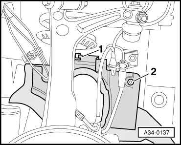
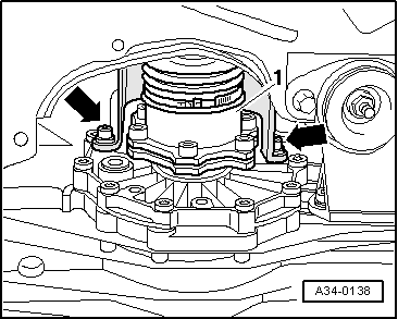
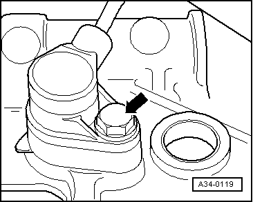
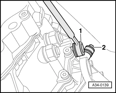
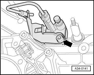
  • ‒ → Remove bolt -arrow- and take out slave cylinder from the rear. Do not open the pipe/hose system.

Note:

Do not depress clutch pedal after removing slave cylinder.

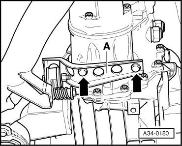
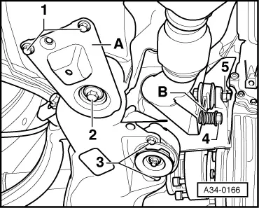
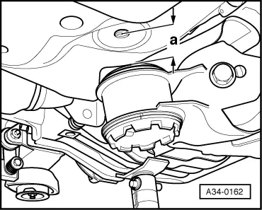
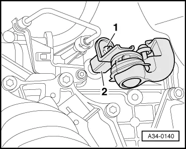
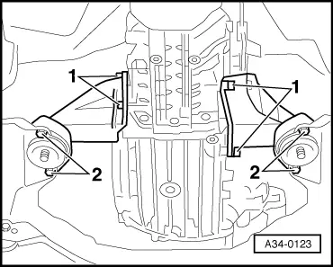
  • ‒ Lower gearbox completely.

Note:

When lowering gearbox ensure there is sufficient clearance to drive shafts.

Installing

Installation is carried out in the reverse order, when doing this note the following:

  • ‒ Renew all seals and gaskets.
  • ‒ Renew all self-locking nuts.
  • ‒ Check whether dowel sleeves for aligning gearbox with engine are in the gearbox flange. Insert if necessary .
  • ‒ Clean input shaft splines and (in the case of used clutch plates) the hub splines. Remove corrosion and apply only a very thin coating of grease G 000 100 to the splines. Do not grease guide sleeve.
  • ‒ Check clutch release bearing for wear and renew if necessary.
  • ‒ Coat contact surface for clutch slave cylinder push rod with a thin layer of copper grease, e.g. Z381 351 TE.
 
A34-0116
  • ‒ → Before installing gearbox, check whether strut -B- is still pivoted to one side (in direction of arrow).
  • ‒ Before installing gearbox, tie electrical wiring off to one side so that it cannot be trapped between the engine and the gearbox.

 
A34-0141
  • ‒ → Lift gearbox until clutch slave cylinder with bracket for pipe/hose can be installed (arrow).
  • ‒ Align exhaust system free of stress

=> 6-cylinder diesel direct injection engine (TDI), Mechanics; Repair group 26; Removing and installing parts of the exhaust system; Aligning exhaust system free of stress

  • ‒ Check adjustment of selector rod and push rod; readjust if necessary => Page 34-16.
  • ‒ Check oil level in gearbox => Page 34-39.
  • ‒ After connecting battery, enter anti-theft code for radio

=> Radio operating instructions

  • ‒ Close windows fully using electric window switches.
  • ‒ Then operate all electric window switches again for at least one second in the "close" direction to activate the automatic one-touch function.
  • ‒ Set clock to correct time.

Tightening torques

 
A10-0193
  • ‒ → Engine/gearbox securing points (illustration shows gearbox flange)

No.

Bolt

Qty.

Nm

1

M 12 x 80

2

65

2

M 12 x 90

1

65

3

M 10 x 50 1)

1

45

4

M 10 x 45

2

45

5

M 10 x 135

1

65

6

M 12 x 110

1

65

7

M 12 x 67

2

65

Dowel sleeves -A- for aligning.

    1)    Special bolt

 
A34-0166

→ Subframe to body

Support -A- to body -arrow 1-

752)

Subframe to body 1)-arrow 2-

115+90°

Gearbox mounting to subframe
-arrow 3-

25

    1)    Always replace bolts

    2)    Different torques=>Fig.1

 
A40-0222

Fig.1    Note different torques

New bolts with a grooved base will be used on vehicles from model year 1998 onwards. These bolts can also be used for older models.

  • ‒ Bolt A - plain base (see arrow)
    Tightening torque: 25 Nm
  • ‒ Bolt B - grooved base (see arrow)
    Tightening torque: 75 Nm

Component

Nm

Clutch slave cylinder to gearbox

20

Gearbox support to gearbox

40

Gearbox support to subframe

20

Engine speed sender -G28

10

Drive shaft to flange shaft

M8
M10

45
80

Heat shield for drive shaft

25

Push rod to gearbox

40

Selector rod to gearbox

25

Connecting rod for selector rod to
gearbox

25

Catalytic converter to mounting lugs

25

Front exhaust pipe to turbocharger

25

Heat shield to turbocharger

10

Clamp for exhaust pipe

40

Bracket for noise insulation to subframe

10

Checking oil level in gearbox > < Checking gear stick setting