audi Workshop Repair Guides

Audi Workshop Service and Repair Manuals

Dismantling and assembling drive pinion > < Dismantling and assembling selector shaft complete
5 & 6-Speed manual gearbox 01E, Front-wheel drive
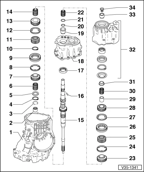
Dismantling and assembling input shaft
 
V35-1341

Notes:

  • ◆ General repair instructions
  • ◆ When installing new gears => Technical data, Page 00-3
  • Gearbox housing
    • ◆ Servicing
  • Needle bearing for input shaft
    • ◆ Pulling out => Fig.34-117
    • ◆ Driving in => Fig.34-117
  • Circlip
    • ◆ For needle bearing
  • Circlip
    • ◆ For input shaft
 
V35-1341
  • Thrust washer
  • Needle bearing for 4th gear
    • ◆ Mark before removing
    • ◆ Do not interchange with needle bearing for 3rd gear
    • ◆ Oil with gear oil before installing
  • 4th speed sliding gear
    • ◆ Before installing, insert spring
      => Fig.1
    • ◆ After installing, check axial clearance with a feeler gauge (0.15 ... 0.35 mm)
  • Synchro-ring for 4th gear
    • ◆ Checking for wear => Fig.2
 
V35-1341
  • Locking collar
    • ◆ Paired with synchro-hub
    • ◆ Mark before removing => Page 34-57
  • Circlip
    • ◆ Re-determine thickness when renewing synchro-hub => Fig.3
    • ◆ Installation position: ends align with groove of synchro-hub
  • Synchro-hub for 3rd and 4th gear
    • ◆ Pressing off => Fig.4
    • ◆ Installation position: => Fig.5
    • ◆ Pressing on => Fig.6
  • Synchro-ring for 3rd gear
    • ◆ Checking for wear => Fig.2
    • ◆ Synchro-ring with molybdenum coating
 
V35-1341
  • 3rd speed sliding gear
    • ◆ Before installing, insert spring
      => Fig.1
    • ◆ After pressing on -item 11-, check axial clearance with a feeler gauge
      (0.15 ... 0.35 mm)
  • Needle bearing for 3rd gear
    • ◆ Mark before removing
    • ◆ Do not interchange with needle bearing for 4th gear
    • ◆ Oil with gear oil before installing
  • Input shaft
  • Spring pin
    • ◆ Always renew
    • ◆ Drive in when renewing input shaft
      => Fig.7
 
V35-1341
  • Cylinder roller bearing for input shaft
    • ◆ Pressing out => Fig.34-96
    • ◆ Pressing in => Fig.34-97
  • Bearing plate
    • ◆ Servicing => Page 34-90
  • Inner race for cylinder roller bearing
    • ◆ Take off and fit by hand
  • Circlip
  • Thrust washer for needle bearing for 6th gear
    • ◆ Not fitted on 5-speed gearbox
    • ◆ Installation position: shoulder towards circlip, smooth contact surface towards needle bearing
      => Page 34-71
 
V35-1341
  • Needle bearing for 6th gear
    • ◆ Not fitted on 5-speed gearbox
    • ◆ Oil with gear oil before installing
  • 6th speed sliding gear
    • ◆ Not fitted on 5-speed gearbox
    • ◆ Before installing, insert spring
      => Fig.1
    • ◆ After installing, check axial clearance with a feeler gauge (0.15 ... 0.35 mm)
  • Synchro-ring for 6th gear
    • ◆ Not fitted on 5-speed gearbox
    • ◆ Checking for wear => Fig.2
  • Synchro-hub for 5th and 6th gear
    • ◆ Pulling off => Page 34-58
    • ◆ Driving on => Page 34-72
    • ◆ Installation position: projecting hub towards 5th speed sliding gear
 
V35-1341
  • Locking collar
    • ◆ Paired with synchro-hub
    • ◆ Mark before removing => Page 34-57
  • Synchro-ring for 5th gear
    • ◆ Checking for wear => Fig.2
  • 5th speed sliding gear
    • ◆ Before installing, insert spring
      => Fig.1
    • ◆ After installing, check axial clearance with a feeler gauge (0.15 ... 0.35 mm)
  • Inner race for 5th speed sliding gear
    • ◆ Pulling off => Page 34-58
    • ◆ Driving on => Page 34-75
  • Needle bearing for 5th gear
    • ◆ Oil with gear oil before installing
 
V35-1341
  • 1st four-point bearing inner race for input shaft
    • ◆ Pulling off => Page 34-56
    • ◆ Driving on
  • End cover
    • ◆ Servicing => Page 34-80
  • 2nd four-point bearing inner race for input shaft
    • ◆ Pulling off => Page 34-55
    • ◆ Driving on => Page 34-76
  • Multi-point socket head bolt
    - 150 Nm
    • ◆ Loosening and tightening
      => Page 34-55
 
V35-1343

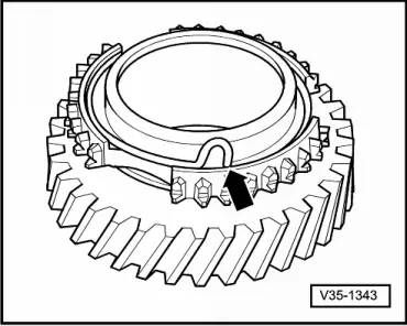
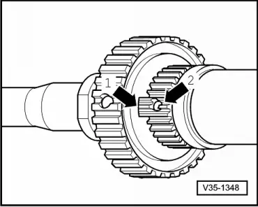
→ Fig.1    Inserting spring in sliding gear

  • ‒ Insert spring -arrow- in sliding gear, hook angled end into hole.

 
V35-1342

→ Fig.2    Checking synchro-ring for wear

  • ‒ Press synchro-ring into locking collar and measure gap "a" with a feeler gauge at positions -A-, -B- and -C-.
  • ‒ Add together results and divide by three.
    • ‒ The figure calculated must not be less than 0.5 mm
 
V35-1347

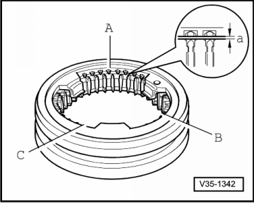
→ Fig.3    Re-determining thickness of circlip

  • ‒ Press synchro-hub onto stop.

Note:

Note correct installation position when pressing on =>Fig.5.

  • ‒ Determine the thickest circlip that can still just be fitted.

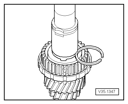
Note:

The opening of the circlip must align with the groove in the synchro-hub.

  • ‒ Determine circlip from table. Part No.

=> Parts catalogue

Circlips available

Circlip thickness (mm)

1.90

1.96

2.02

1.93

1.99

2.05

  • ‒ Fit circlip.
 
V35-1344

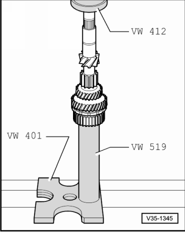
→ Fig.4    Pressing off synchro-hub for 3rd and 4th gear

 
V35-1348

→ Fig.5    Synchro-hub installation position

  • ◆ Oil groove in synchro hub -arrow 1- must align with oil drilling -arrow 2- in input shaft
 
V35-1345

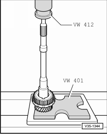
→ Fig.6    Pressing on synchro-hub for 3rd and 4th gear

  • ‒ Heat synchro-hub to approx. 100 °C, fit and press home.
  • ‒ Fit circlip.

 
V35-1349

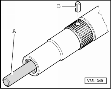
→ Fig.7    Driving spring pin into input shaft

  • ‒ Guide a 9 mm diameter drift -A- into oil drilling and drive spring pin -B- in until it touches drift.

Dismantling and assembling drive pinion > < Dismantling and assembling selector shaft complete