
A4 Mk1
|
Servicing clutch mechanism
Removing and installing master cylinder
|
 |
|
|
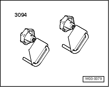
Special tools, testers and other items required
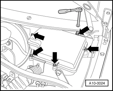
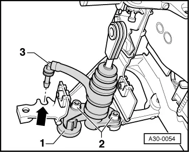
Removing
|
 |
|
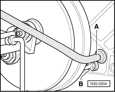
Old version with assembly hole in cowl panel grille:
|
 |
|
|
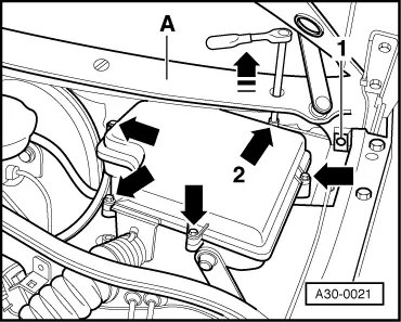
New version with no assembly hole in cowl panel grille:
All models:
|
 |
|
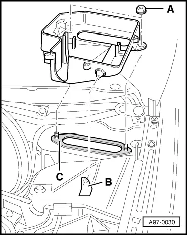
Notes:
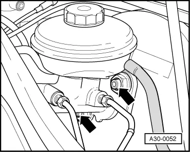
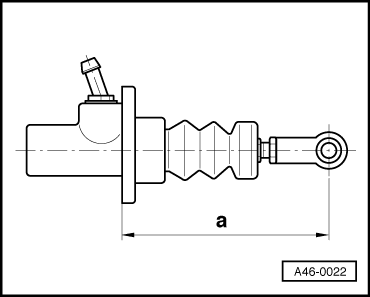
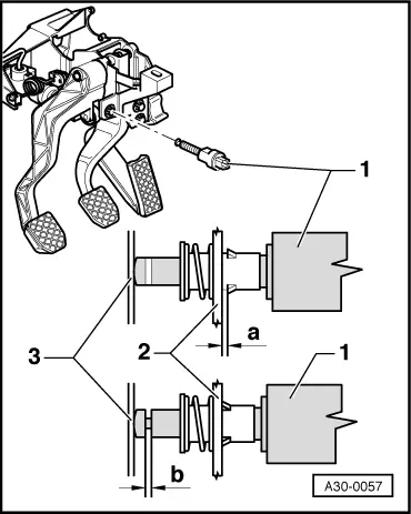
Old version with aluminium master cylinder: |
 |
|
|
 |
|
|
New version with plastic master cylinder: |
 |
|
|
All models:
|
 |
|
Note: |
 |
|
|
 |
|
|
|
|
|
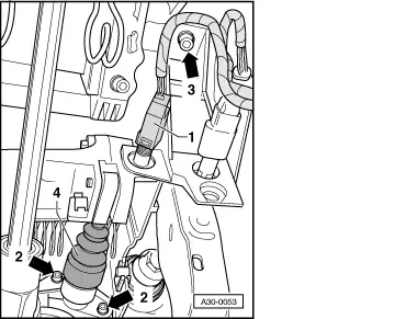
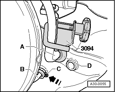
A second mechanic is required for the next operation.
|
|
|
|
|
|
|
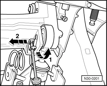
Old version with aluminium master cylinder:
New version with plastic master cylinder: |
 |
|
|
 |
|
|
All models:
|
 |
|
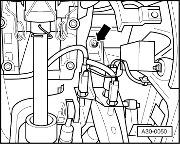
Note: Switch is only to be fitted once so as to ensure a firm fit. |
|
|
|