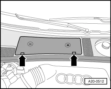
audi Workshop Repair Guides

Audi Workshop Service and Repair Manuals

Removal on vehicles with V6 TDI engine > < Removing and installing gearbox
6-speed manual gearbox 01E Four-wheel drive
Removing and installing gearbox
Removal on vehicles with 4-cyl. TDI engine

Special tools and workshop equipment required

  • ◆ Support bar 10-222 A
  • ◆ Gearbox mount 3282
  • ◆ Adjustment plate 3282/12
  • ◆ Engine/gearbox lifter V.A.G 1383 A

Note:

All cable ties unfastened or cut open on removal are to be re-attached in same position on installation.

 
A20-0512
Attention:
Heed appropriate instructions for battery disconnection. =>Electrical System; Repair Group 27
  • ‒ Heed (if necessary obtain) code for vehicles with encoded radio/radio navigation system (RNS).
  • ‒ → Remove cover over battery -arrows-.

 
A20-0513
  • ‒ → Disconnect earth strap -arrow- at battery with ignition switched off.
 
A34-0538
  • ‒ → Pull dipstick -1- out of guide tube.
  • ‒ Unclip caps.
  • ‒ Unfasten nuts -arrows- and detach engine cover.
  • ‒ Re-insert dipstick in guide tube.

 
A34-0429
  • ‒ → Position support bar 10-222 A on wing mounting flange with spindle at front.
  • ‒ Engage hook of spindle in shackle at front of engine -arrow-.
  • ‒ Slightly pretension engine with spindle of support bar.
 
A10-0407
  • ‒ Unscrew both front wheels.
  • ‒ → On vehicles with auxiliary heater, screw out bolts -arrows- for exhaust pipe of auxiliary/additional heater at noise insulation.

 
A34-0539
  • ‒ → Release fasteners -1 ... 4- and remove noise insulation (2 sections).
 
A10-0968
  • ‒ → Unscrew bracket for noise insulation -arrows-.

 
A10-0768
  • ‒ → Slacken off bolt -1- of noise insulation over left and right drive shaft.
  • ‒ Disengage hook -2- and detach noise insulation.
 
A10-0961
  • ‒ → Detach heat shield -1- over right drive shaft from gearbox -arrows-.
  • ‒ Unscrew drive shafts on left and right from gearbox flange.

=> Running Gear, Front-wheel Drive and Four-wheel Drive; Repair Group 40; Removing and installing drive shaft

 
A34-0541
  • ‒ → Unscrew front exhaust pipe at catalytic converter -arrows-.

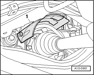
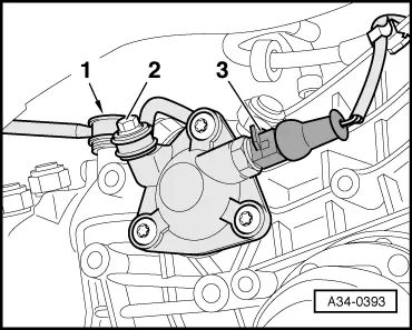
Note:

To avoid damage, decoupling element upstream of catalytic converter is never to be kinked by more than 10 °.
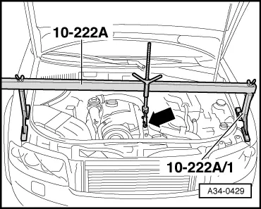
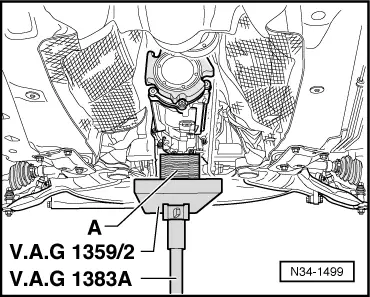
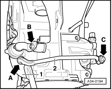
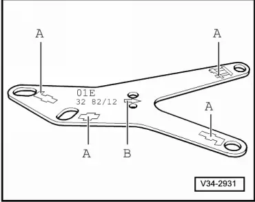
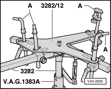
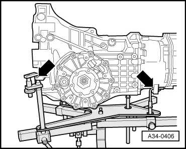
 
V26-0733
  • ‒ → Separate exhaust system at clamp -arrows- and take out front exhaust pipe.

 
A34-0128
  • ‒ → Unscrew propshaft -1- at gearbox and set down on heat shield -2-.
  • ‒ Use wire -arrow- to attach propshaft to holder -3- of fuel pipes.
 
A34-0433
  • ‒ → Screw out the three engine/gearbox connecting bolts at bottom
    -arrow-.

 
N34-1499
  • ‒ → Use engine/gearbox lifter V.A.G 1383 A to provide some support for gearbox.

A - Wooden block

 
A34-0540
  • ‒ → If applicable, screw out bolts -1- and detach cross member -A-.
  • ‒ Screw out bolts -2- and -3- on both sides and detach supports -B-.

 
A34-0162
  • ‒ → Lower gearbox lifter V.A.G 1383 A until subframe is released at rear.
  • ◆ Dimension -a- max. 50 mm
 
A34-0393
  • ‒ → Unscrew connecting rod -2- on right side of gearbox.
  • ‒ Screw out 8 mm hexagon socket-head bolt of push rod -1-.
  • ‒ Unplug connector -3- for reversing light switch on right of gearbox and lay bare wire.

Note:

Packing plates may have been fitted between gearbox and push rod. If this is the case, they must be inserted again on assembly.

 
A34-0194

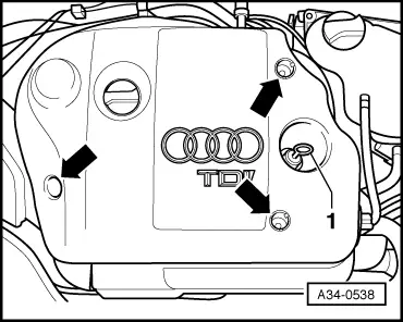
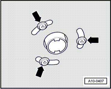
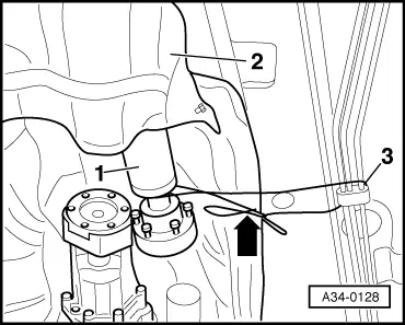
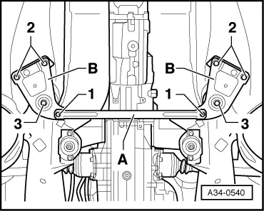
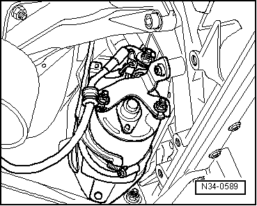
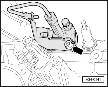
Important note on subsequent operations:

→ When removing shift mechanism (up to approx. 11.00), never detach ball end -arrow A- of connecting rod -2- from selector rod -1-.

Detaching would destroy ball end.

 
A34-0140
  • ‒ → Unscrew nut -1- and pull lever -2- of selector rod off gearbox selector shaft.

 
A34-0498
  • ‒ → Unplug connector -arrow-at speedometer sender -G22 on left of gearbox.
 
A34-0119
  • ‒ → If fitted, remove engine speed sender -G28 on left of gearbox -arrow- and lay aside.

 
N34-0589
  • ‒ → Detach starter from engine/gearbox and secure if necessary.

=> Electrical System; Repair Group 27; Removing and installing starter

Note:

Starter cables do not have to be disconnected.

  • ‒ With the exception of one holding bolt, screw out all engine/gearbox connecting bolts from underneath.
 
V34-2931

Notes:

  • ◆ → Mounting elements -A- are illustrated symbolically, arrow -B- faces in direction of travel.
  • ◆ Adjustment plate 3282/12 only fits in one position.

 
V34-2930
  • ‒ → Position gearbox mount 3282 on gearbox lifter V.A.G 1383 A.
  • ‒ Align arms of gearbox mount to coincide with holes in adjustment plate.
  • ‒ Screw in mounting elements -A- as shown on adjustment plate.
 
A34-0406
  • ‒ → Position gearbox lifter V.A.G 1383 A with gearbox mount 3282 beneath gearbox and attach as shown to left ...

 
A34-0407
  • ‒ → ... and right side of gearbox.
 
A34-0123
  • ‒ Detach heat shield over right gearbox support.
  • ‒ → Screw out bolts -2- for bonded rubber bushes on left and right.
  • ‒ Raise gearbox slightly.
  • ‒ Screw out bolts -1- and detach supports on left and right of gearbox.
  • ‒ Move drive shafts to rear.
  • ‒ Screw out remaining engine/gearbox connecting bolt.
  • ‒ Press gearbox off dowel sleeves and carefully lower slightly using gearbox lifter V.A.G 1383 A until slave cylinder just becomes accessible.

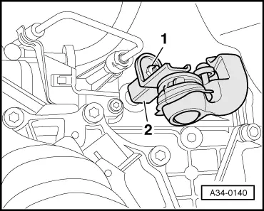
Note:

On lowering gearbox, take care not to damage hydraulic pipe to slave cylinder.

 
A34-0141
  • ‒ → Screw out bolt -arrow- and pull out clutch slave cylinder to rear.
    Do not open piping system.

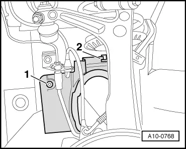
Note:

Do not press clutch pedal after removing slave cylinder.

  • ‒ Completely set down gearbox.

Note:

On lowering, ensure clearance with respect to drive shafts.

Removal on vehicles with V6 TDI engine > < Removing and installing gearbox