audi Workshop Repair Guides

Audi Workshop Service and Repair Manuals

Pressing clutch -K1- onto clutch -K3- > < IV - Installing components from supporting tube for -B2- up to ATF pump
Automatic gearbox 01N
Dismantling and assembling planetary gearbox
Assembling planetary gearbox
 
G37-0014

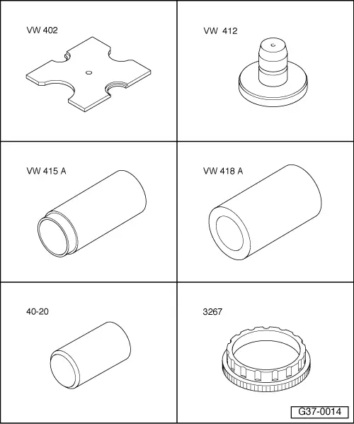
Special tools and workshop equipment required

  • ◆ Thrust plate VW 402
  • ◆ Press tool VW 412
  • ◆ Tube VW 415 A
  • ◆ Tube VW 418 A
  • ◆ Drive sleeve 40-20
  • ◆ Assembly ring 3267
 
N37-0008

Assembling planetary gearbox

  • ‒ → Fit O-ring -arrow- into planet carrier.

Notes:

  • ◆ Use all parts of the exchange component when installing; do not use old parts.
  • ◆ The planet carrier should be adjusted after replacing either the planet carrier, the large sun gear, the large input shaft or the small input shaft.
 
A37-0152
  • ‒ → Insert axial needle bearing with washers and planet carrier in the input gear.
  •     1 -    Install planet carrier with O-ring fitted
  •     2 -    Washer for axial needle bearing
  •     3 -    Axial needle bearing
  •     4 -    Washer for axial needle bearing; smooth side faces toward input gear
  •     5 -    Input gear; is fitted in gearbox housing
 
N37-0463

Gearboxes with code letters DMU, DMV, DMX, EPT, EPU, EPV:

  • ‒ → Inserting small sun gear with washer and axial needle bearing into planet carrier.
  •     1 -    Axial needle bearing
  •     2 -    Washer for axial needle bearing
  •     3 -    Small sun gear
  •     4 -    Planet carrier
  • ‒ Centralize washer and axial needle bearing in small sun gear.

 
N37-0882

Gearboxes with other code letters:

  • ‒ → Place washer -2- and axial needle bearing -1- on the "small sun gear" in the planet carrier -3-.
  • ‒ Centralize washer and axial needle bearing in small sun gear.

All models

  • ‒ Insert shim(s).
  • ‒ Insert inner and outer -B1- plates.
  • ‒ Insert pressure plate of -B1- with flat side facing plates.

Note:

Thickness of pressure plate varies according to number of plates The replacement pressure plate is assigned to the gearbox code letters.

 
N37-0469
  • ‒ → Insert dished washer with convex side facing towards freewheel.

Note:

When replacing the following components, adjust the reverse gear brake -B1- => Page 37-141:

  • ◆ Free wheel
  • ◆ Piston for reverse gear brake -B1-
  • ◆ Plates
  • ◆ Gearbox housing
 
N37-0427
  • ‒ → Preload freewheel rollers with assembly ring 3267 and insert free wheel.

 
N37-0881
  • ‒ → Installation position of free wheel: The retaining wedge (arrow) must be seated in the machined groove on gearbox housing.
  • ‒ Fit circlip -b- for free-wheel.
  • ‒ Fit open ends of circlips facing toward retaining wedge (arrow) of free-wheel.
  • ‒ Insert baffle block -2- in gearbox housing groove, where ATF breather drilling -1- is located.
 
N37-0011
  • ‒ → Install circlip -a- for supporting tube for -B2- with open ends of circlip facing toward retaining wedge -arrow- of free wheel.
  • ‒ Perform check measurement of -B1-.
  • ‒ Install gearbox speed sender -G38.

 
A37-0155
  • ‒ → Install the parts in the gearbox housing in the reverse order of the numbering:
  • 1 - Small drive shaft
  • 2 - Needle bearing
  • 3 - Axial needle bearing
  • 4 - Large drive shaft
  • 5 - Axial needle bearing
  • 6 - Washer for axial needle bearing
    (shoulder faces toward large sun gear)
  • 7 - Large sun gear
 
A37-0133
  • ‒ → Install bolt -1- for small drive shaft with washer -2- and shim -3-.
  • ‒ Tighten bolt to 30 Nm.

Notes:

  • ◆ Insert shim -3- onto small input shaft shoulder (arrow).
  • ◆ Determining shim thickness => adjusting planet carrier, Page 37-133.
  • ‒ Carry out planet carrier check measurement => Page 37-140.

 
N38-0022
  • ‒ → Insert new O-ring in the recess in the turbine shaft (arrow).
  • ‒ Moisten O-ring with ATF.
 
N37-0493

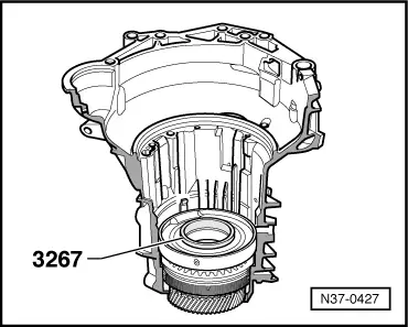
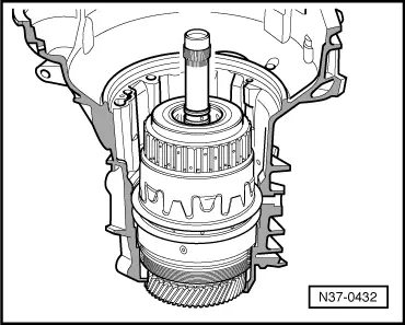
Note:

On some gearboxes the clutches -K1- and -K3- must be pressed together before installing.

  • ‒ Check that clutch -K1- can be fitted completely onto turbine shaft splines of -K3-.
  • ‒ Do this by fitting -K1- onto -K3- by hand.
    • ‒ → If splines (arrow 1) are visible in hub of -K1-, the clutches must be pressed together => Page 37-130.

 
N37-0596
    • ‒ → If the resistance of the O-ring is overcome when fitting the clutches together by hand, the splines -arrow 1 - of -K1 are no longer visible. In this case the clutches do not have to be pressed together.
  • Continue to assemble the gearbox.
 
N37-0047
  • ‒ → Fit axial needle bearing together with washer -1- onto 3rd and 4th gear clutch -K3- , -Item 2-.
    • ‒ Installation position: bearing washer faces toward -K3-.

Notes:

  • ◆ Lubricate axial bearing washer with ATF to make sure that it adheres to -K3-.
  • ◆ Shown in illustration on clutches which were not pressed together.

 
N38-0023
  • ‒ → Ensure piston rings seat correctly on -K3-.
  • ‒ Ensure that the ends of the piston rings are hooked together.
 
N37-0430
  • ‒ → Inserting 3rd and 4th gear clutch -K3-.

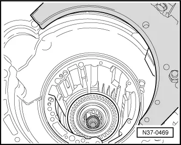
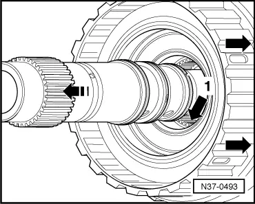
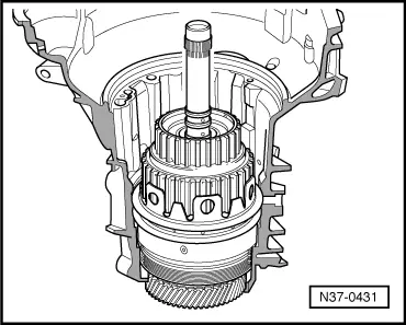
Note:

When installing, rotate 3rd and 4th gear clutch -K3- until all the plates have meshed.

  • ‒ Fit seal -1- in the groove (arrow).
  • ‒ Moisten O-ring with ATF.

 
N37-0431
  • ‒ → Inserting 1st to 3rd gear clutch -K1-.

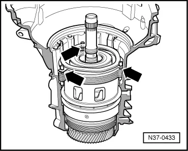
Note:

If clutches -K1- and K3- are pressed together, they can only be installed as one unit.

 
N37-0210
  • ‒ → Insert shim(s) -arrow- in -K1-.

Notes:

  • ◆ The shim thickness must be recalculated when replacing -K1-, -K2-, the small input shaft or the ATF pump, => Adjusting clutch play between -K1- and -K2-, Page 37-149.
  • ◆ 1, 2 or 3 shims can be installed.

 
N37-0432
  • ‒ → Insert reverse gear clutch -K2-.

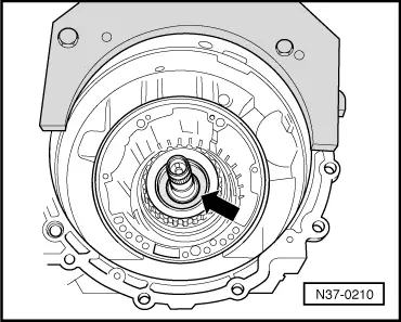
Note:

When installing, rotate reverse gear clutch -K2- until all the plates have meshed.

  • ‒ Insert supporting tube for plate set of 2nd and 4th gear brake -B2- so that recess on lower part of supporting tube engages in retaining wedge of free wheel.

Note:

When replacing the following components, adjust the 2nd and 4th gear brake -B2- :

  • ◆ Gearbox housing
  • ◆ Supporting tube
  • ◆ ATF pump
  • ◆ Corrugated spring washer
  • ◆ Retaining ring
  • ◆ Plates

These components are allocated as replacement parts according to gearbox code letters.

 
N37-0433
  • ‒ → Install -B2- 2nd and 4th gear brake plates as follows:
    • ‒ First insert a 3 mm thick outer plate.
    • ‒ Fit three spring caps into the outer plate.
    • ‒ Insert the compression springs (arrows).
    • ‒ Insert all the plates with the exception of the last outer plate.
    • ‒ Fit three spring caps onto compression springs.
 
N37-1066

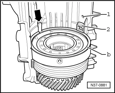
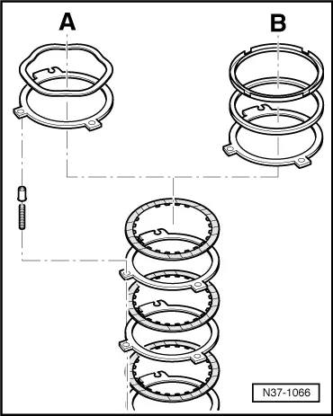
There are two versions of brake -B2-:

  •     A -    Brake with corrugated spring washer
  •     B -    Brake with retaining ring

Gearboxes with a corrugated spring washer installed on the last outer plate of brake -B2-

(code letters => from Page 00-3):

Note:

On these gearboxes the play of brake -B2- is determined by the thickness of the last outer plate. Calculating thickness of last outer plate.

  • ‒ Insert last (measured) outer plate.

Note:

If it is necessary to fit two outer plates because of the results of the measurement, these should be fitted together on the spring caps.

  • ‒ Install corrugated washer
 
N37-0542

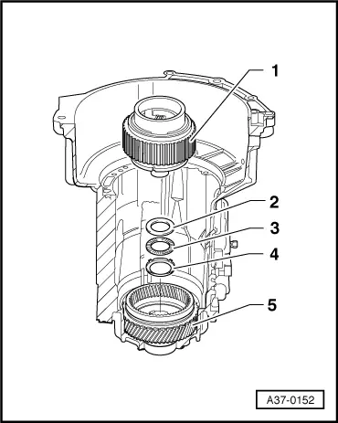
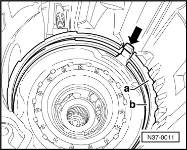
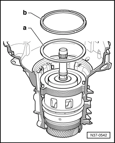
Gearboxes with a shim and a retaining ring installed in brake -B2- (code numbers => from Page 00-3):

Note:

→ On these gearboxes, the thickness of the last outer plate is always 3 mm. The play of brake -B2- is determined by shim -a- onto which retaining ring -b- is inserted.

  • ‒ Insert last outer plate -3 mm thick-.
  • ‒ Determine thickness of shim => Page 37-156 and insert.
  • ‒ Fit retaining ring onto shim.
    • ‒ Fitting position: smooth side facing shim

 
N37-0742

All models

  • ‒ → Clean and install strainer if fitted.

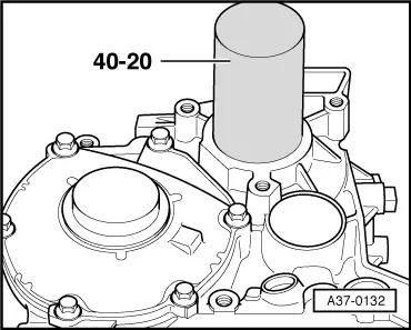
Note:

The strainer is located in the return pipe of the ATF cooler. It cannot be retrofitted on earlier gearbox versions.

 
N37-0434
  • ‒ Install ATF pump gasket, noting position of holes.
  • ‒ Fit O-ring on ATF pump..

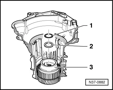
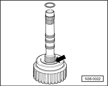
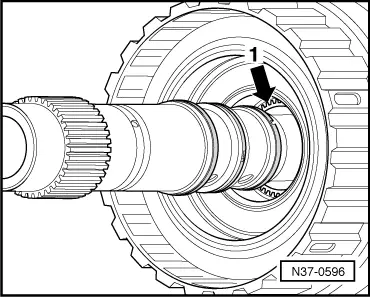
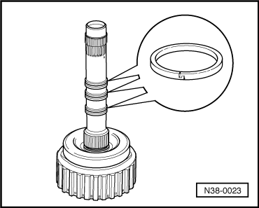
Note:

Ensure the piston rings are properly seated.

  • ‒ → Install ATF pump so that holes for securing bolts are correctly positioned.
  • ‒ Tighten bolts evenly, crosswise, to 8 Nm.

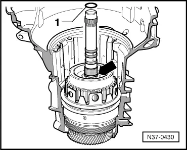
Note:

Ensure that the O-ring is not damaged.

  • ‒ Then turn bolts 90 ° further.
  • Turning further can be done in several stages.
  • ‒ Carry out check measurement of clutch play => Page 37-155.
 
A37-0132
  • ‒ → Drive in cover with drive sleeve 40-20.
  • ‒ Install gearbox speed sender -G38 =>Page38-61.

 
A38-0021
  • ‒ → Insert sealing plugs with O-rings.
    • ‒ Installation position: lug -arrow- fits into oil passage.
  • ‒ Install valve body with conductor strip => from Page 38-27.
  • ‒ Install oil pan => from Page 38-27.
  • ‒ Install torque converter=>from Page 32-3.
  • ‒ Cleaning ATF lines and cooler => page 37-80.
  • ‒ Install gearbox => Page 37-49.
  • ‒ Fill up with ATF and check ATF level => Page 37-59.

Pressing clutch -K1- onto clutch -K3- > < IV - Installing components from supporting tube for -B2- up to ATF pump