A4 Mk1
|
Removing and installing gearbox
Removing and installing gearbox
|
 |
|
|
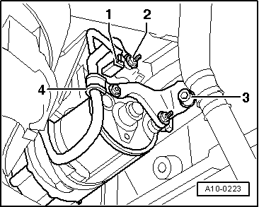
Vehicles with 1.8 ltr. petrol engine:
|
 |
|
|
Vehicles with TDI engine:
|
 |
|
|
 |
|
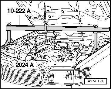
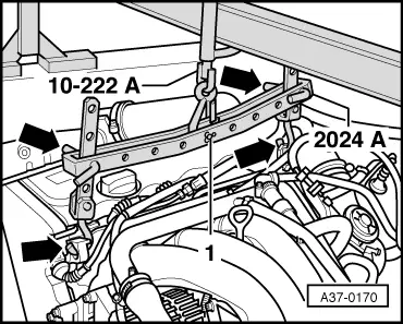
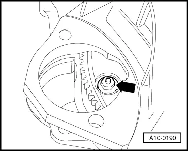
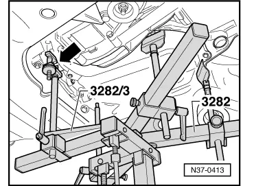
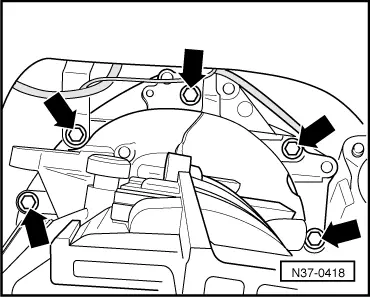
Warning
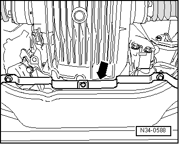
The hook attachments and locating pins on the lifting tackle must be secured with locking pins (arrows in illustration).
|
 |
|
Vehicles with petrol engine:
Vehicles with TDI engine:
|
 |
|
|
 |
|
|
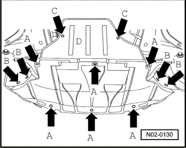
All models
|
 |
|
|
 |
|
|
 |
|
=> Running gear, Front and four-wheel drive; Repair group 40; Removing and installing drive shaft
Notes:
Vehicles with petrol engine and without air conditioner
|
 |
|
|
Vehicles with petrol engine and air conditioner and vehicles with TDI engine:
|
 |
|
|
All models
|
 |
|
|
 |
|
|
 |
|
|
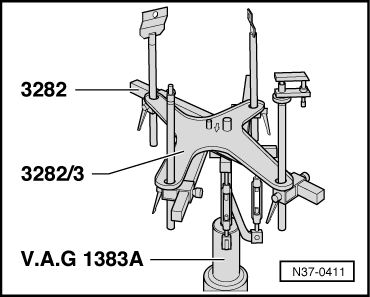
Vehicles with petrol engine and without air conditioner
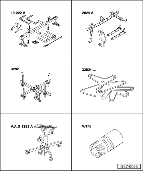
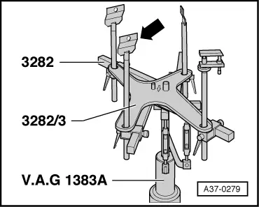
The gearbox mount 3282 is set up with the adjusting plate 3282/2 for removing the automatic gearbox 01N. The symbols on the adjusting plate indicate the mounts required, the arrow points forward. |
 |
|
|
 |
|
|
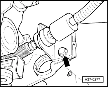
Vehicles with petrol engine and air conditioner and vehicles with TDI engine
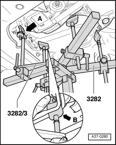
Attach a retainer plate -arrow- in place of the retainer pin (the set-up is not as indicated by the symbols on the adjustment plate). |
 |
|
|
 |
|
|
All models
|
 |
|
Installing Install in reverse sequence; note the following points: Notes:
|
|
|
Notes:
|
 |
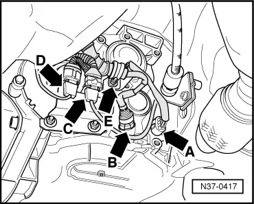
|||||||||||||||||||
|
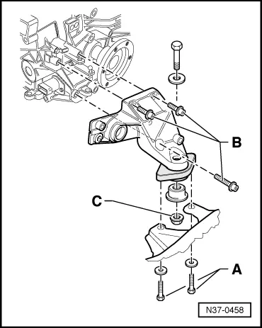
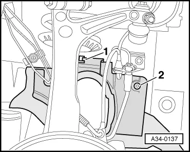
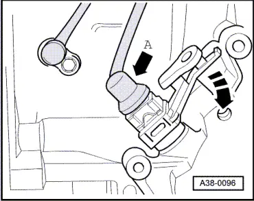
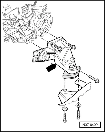
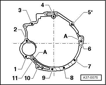
1.6 ltr. engine: → Engine/gearbox mountings
A: centering sleeves |
|
|||||||||||||
|
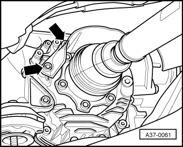
1.8 ltr. petrol engine, 1.9 ltr. TDI engine: → Engine/gearbox mountings
A: centering sleeves |
|
|
|
All models
=> Parts catalogue
|
|
|
=> Electrical system; Repair group 27; Removing and installing starter
=> Running gear, Front and four-wheel drive; Repair group 40; Removing and installing drive shaft
Notes:
|