-
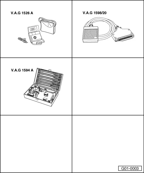
‒ → For all test steps, switch off ignition, unplug multi-pin connector from automatic gearbox control unit -J217 (control unit is located in front of right seat beneath cover in footwell => Page 01-6) and connect test box V.A.G 1598/20 to wiring harness connector.
-
‒ If readings do not match specifications, perform "Measures to be taken if reading does not match specification" as listed on right of test table.
-
‒ Perform all measures listed in column "Measures to be taken if reading does not match specification".
-
‒ Only perform test steps recommended in fault table (specific testing).
Multi-pin connector (88-pin) of automatic gearbox control unit -J217 (sockets on V.A.G 1598/20)
|
1-
|
Solenoid valve 5 -N92
|
18-
|
Kickdown switch -F8 (not with electronic throttle
and V6-TDI)
|
|
2-
|
Selector lever lock solenoid -N110
|
19-
|
Gearshift by ABS control unit
|
|
3-
|
Not used
|
20-
|
Engine intervention (ignition point adjustment) 1)
|
|
4-
|
Solenoid valve 7 -N94
|
21-
|
Gearbox oil temperature sender -G93 (ATF)
|
|
5-
|
Solenoid valve 4 -N91
|
22-
|
Gearbox oil temperature sender -G93 (ATF)
|
|
6-
|
Earth for loads (terminal 31)
|
23-
|
Gearbox input speed sender -G182 (screen)
|
|
7-
|
Not used
|
24-
|
Not used
|
|
8-
|
Multi-function switch -F125 L2
|
25-
|
Selector lever position indicator (not for highline dash panel insert)
|
|
9-
|
Multi-function switch -F125 L4; supply voltage for cruise control system
|
26-
|
Supply voltage (terminal 30), with or without fuse depending on design status => Current flow diagram
|
|
10-
|
Brake light switch -F (not with electronic throttle
and V6-TDI)
|
27-
|
Kickdown for air conditioner 1)
|
|
11-
|
Not used
|
28-
|
Earth for electronics (terminal 31) 4)
|
|
12-
|
Not used
|
29-
|
Solenoid valve 6 -N93
|
|
13-
|
Tiptronic recognition
|
30-
|
Solenoid valve 1 -N88
|
|
14-
|
Gearbox speed sender -G38
|
31-
|
Not used
|
|
15-
|
Gearbox speed sender -G38 (screen)
|
32-
|
Solenoid valve 3 -N90
|
|
16-
|
Gearbox input speed sender -G182
|
33-
|
Solenoid valve 2 -N89
|
|
17-
|
Signal for fault display (OBD II requirement) 1) 2)
|
34-
|
Earth for loads (terminal 31)
|
Notes and footnotes on assignment of multi-pin connector => Page 01-287
|
35-
|
Fuel consumption signal (engine actual torque) 1)
|
54-
|
Supply voltage (terminal 15)
|
|
36-
|
Multi-function switch -F125 L1
|
55-
|
Supply voltage (terminal 15)
|
|
37-
|
Multi-function switch -F125 L3
|
56-
|
Not used
|
|
38-
|
Not used
|
-
|
|
|
39-
|
Not used
|
-
|
|
|
40-
|
Engine speed signal 1)
|
-
|
|
|
41-
|
Throttle valve value (load signal) 1)
|
-
|
|
|
42-
|
Gearbox speed sender -G38
|
-
|
|
|
43-
|
Not used
|
-
|
|
|
44-
|
Gearbox input speed sender -G182
|
-
|
Sockets 57 - 83 not used
|
|
45-
|
Not used
|
-
|
|
|
46-
|
Tiptronic change-up
|
-
|
|
|
47-
|
Tiptronic change-down
|
-
|
|
|
48-
|
Not used
|
-
|
|
|
49-
|
Not used
|
84-
|
Not used
|
|
50-
|
Not used
|
85-
|
CAN bus 3)
|
|
51-
|
Change-up/change-down signal (for engine
intervention) 1)
|
86-
|
CAN bus 3)
|
|
52-
|
Supply voltage for solenoid valves
|
87-
|
Not used
|
|
53-
|
Supply voltage for solenoid valves
|
88-
|
Diagnosis K-wire
|
Notes and footnotes on assignment of multi-pin connector => Page 01-287
Notes and footnotes on assignment of multi-pin connector
1) Vehicles with no CAN bus only
=> Automatic Gearbox 01V Front and Four-Wheel Drive; Repair Group 00; Code letters, assignment of mechanical units, transmission ratios, features
2) Signal is transmitted via engine control unit to gearbox control unit and can only be checked in measured value block => Page 01-194.
3) Vehicles with CAN bus only. For further information on CAN bus, refer to => Page 01-271
=> Automatic Gearbox 01V Front and Four-Wheel Drive; Repair Group 00; Code letters, assignment of mechanical units, transmission ratios, features
4) Control-unit pin 28 is not used on vehicles with 10-pin connector for multi-function switch -F125.
List of test steps (88-pin connector)
|
Component checked
|
|
Component checked
|
|
|
Automatic gearbox control unit -J217 supply voltage
|
- Perform test steps 1
and 7
|
Solenoid valve 5 -N92
(pressure control valve 2 -N216)
|
- Perform test steps 13
and 8
|
|
Selector lever lock solenoid -N110
|
- Perform test steps 2, 6 and 16
|
Solenoid valve 6 -N93
(pressure control valve 3 -N217)
|
- Perform test steps 14
and 8
|
|
Brake light switch -F
|
- Perform test step 3
|
Solenoid valve 7 -N94
(pressure control valve 4 -N218)
|
- Perform test steps 15
and 8
|
|
Supply voltage for cruise control system
|
- Perform test step 4
|
Gearbox speed sender -G38(gearbox output speed sender -G195)
|
- Perform test step 18
|
|
Kickdown switch -F8
(not for V6 TDI and electronic throttle)
|
- Perform test steps 5
and 17
|
Gearbox input speed sender -G182
|
- Perform test step 19
|
|
Multi-function switch
(driving range sensor) -F125
|
- Page => 01-314
|
Gearbox oil temperature sender -G93 (ATF)
|
- Perform test step 20
|
|
Solenoid valve 1 -N88
|
- Perform test steps 8
and 9
|
Wiring to engine control unit 1)
|
- Perform test steps 21, 22, 23, 24 and 25
|
|
Solenoid valve 2 -N89
|
- Perform test steps 10 and 8
|
Tiptronic switch -F189
|
- Perform test steps 26 and 27
|
|
Solenoid valve 3 -N90
|
- Perform test steps 11
and 8
|
CAN bus 2)
|
- Test step 28 and check bus system => Page 01-273
|
|
Solenoid valve 4 -N91
(pressure control valve 1 -N215)
|
- Perform test steps 12
and 8
|
|
|
1) Signal is transmitted via engine control unit to gearbox control unit (checking for vehicles with no CAN bus only)
=> Automatic Gearbox 01V Front and Four-Wheel Drive; Repair Group 00; Code letters, assignment of mechanical units, transmission ratios, features
2) Checking for vehicles with CAN bus only
=> Automatic Gearbox 01V Front and Four-Wheel Drive; Repair Group 00; Code letters, assignment of mechanical units, transmission ratios, features
|