audi Workshop Repair Guides

Audi Workshop Service and Repair Manuals

Removing and installing coolant pump > < Cooling system components
4-Cyl. TDI®Engine, Mechanics
Removing and installing cooling system components
Draining and filling cooling system
 
G19-0006

Special tools and workshop equipment required

  • ◆ Adapter V.A.G 1274/8
  • ◆ Pipe V.A.G 1274/10
  • ◆ Drip tray V.A.G 1306
  • ◆ Hose clamp fitting tool V.A.G 1921
  • ◆ Special tool T10007

Draining

Note:

Coolant drained off must be collected in a clean container for disposal/re-use.

Attention:
Hot vapour may escape when opening expansion tank. Cover cap with cloth and open carefully.
  • ‒ Unscrew cap of coolant expansion tank.
 
A19-0220
  • ‒ → Detach vacuum hose -arrow- from vacuum unit of fuel cooling circuit cut-off valve.
 
A10-0658
  • ‒ → Release quick-release fasteners -1- and -2- and detach front noise insulation. Do not remove rear noise insulation.

 
A10-0347
  • ‒ Place drip tray V.A.G 1306 below engine.
  • ‒ → Disconnect bottom coolant hose from radiator -arrow-.
 
A10-0020

Note:

→ When the bumper is removed, the coolant can also be drained from the radiator via the drain plug -arrow-.

 
A19-0221
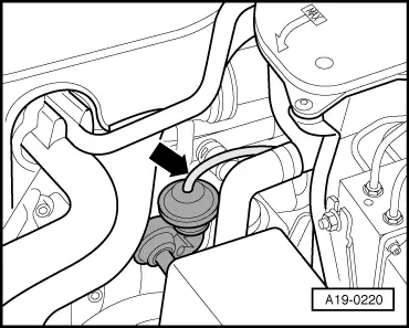
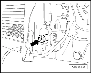
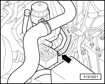
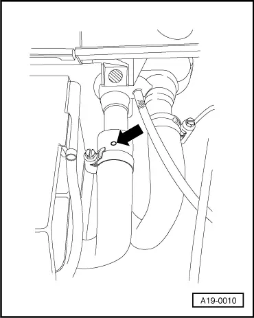
  • ‒ → To drain off the remaining coolant, disconnect coolant hose -arrow- from oil cooler.

Filling

Notes:

  • ◆ The cooling system is filled all year round with a mixture of water and radiator anti-freeze/anti-corrosion agent.
  • ◆ Exclusive use is to be made as coolant additive of G 012 A8 D as per TL VW 774 D.
    Identifiable by: red colour
Attention:
Use only coolant additive G
  • ◆ If fluid in expansion tank is brown, G 012 A8 D has been mixed with a different type of coolant. In this case, flush out cooling system and replace coolant. To flush out, fill cooling system with clean water and allow engine to run for approx. 2 minutes. This should remove virtually all the old coolant.
  • ◆ G 012 A8 D and coolant additives marked "meeting specification TL VW 774 D" prevent frost and corrosion damage, stop scale forming and at the same time raise the boiling point of the coolant. The cooling system must therefore be filled all year round with anti-freeze and anti-corrosion additive.
  • ◆ On account of the higher boiling point, the coolant helps to enhance engine reliability under heavy loads particularly in countries with tropical climates.
  • ◆ Frost protection must be guaranteed to around -25 °C (in countries with arctic climate to around -35 °C).
  • ◆ The coolant concentration must not be reduced by adding water even in warmer seasons and in warmer countries. The anti-freeze ratio must be at least 40 %.
  • ◆ If greater frost protection is required in very cold climates, the amount of G 012 A8 D can be increased, however only up to 60 % (giving frost protection to around -40 °C), otherwise frost protection decreases again and cooling efficiency is also impaired.
  • ◆ Exclusive use is to be made of clean drinking water for mixing coolant.
  • ◆ If the radiator, heat exchanger, cylinder head, cylinder head gasket or cylinder block has been replaced, do not re-use used coolant.
  • ◆ Always replace gaskets and sealing rings.
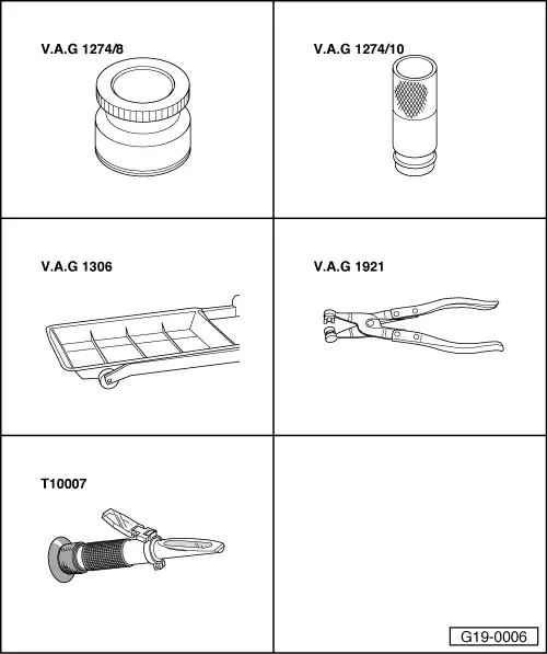
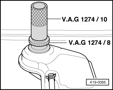
  • ◆ For checking anti-freeze protection in cooling system, use must be made for coolant additive G012 A8 D of the special tool T10007.

Recommended mixing ratios:

Frost protection to

Anti-freeze part

G 012A8 D 1)

Water 1)

-25 °C
-35 °C

40 %
50 %

3.0 l
3.5 l

4.0 l
3.5 l

    1)    Coolant 7.0 litres; may vary depending on vehicle specification.

  • ‒ Fit and secure coolant hoses.
  • ‒ Close drain plug at radiator.
 
A19-0065
  • ‒ → Screw adapter V.A.G 1274/8 onto coolant expansion tank.
  • ‒ Fit special tool V.A.G 1274/10 onto adapter.

Note:

To charge without using the special tool, detach the expansion tank and raise it approx. 100 mm.

 
A20-0564
  • ‒ → Remove rubber seal from front of plenum chamber cover -arrows-.
  • ‒ Remove plenum chamber cover -1- from the front.

 
A19-0010
  • ‒ Fold back bellows at heater heat exchanger connection in plenum chamber.
  • ‒ → Detach coolant hose from heat exchanger and pull it back until vent hole in coolant hose -arrow- is no longer concealed by connection.
  • ‒ Charge coolant until it emerges from vent hole in coolant hose.
  • ‒ Push coolant hose onto connection and secure it.
  • ‒ Seal expansion tank.
 
A01-0128
  • ‒ Start final control diagnosis and activate fuel cooling pump relay
    -J445.

→ Readout on VAS 5051:

  •     A -    6th control element in test
  •     6 -    Fuel cooling pump relay -J445
  • ◆ The fuel cooling pump relay -V166 is switched on and off at intervals over a period of about 30 seconds (audible at right in engine compartment).
  • ‒ Terminate function "03 - Final control diagnosis" by touching ◂ key.

 
A19-0220
  • ‒ → Refit vacuum hose -arrow- onto vacuum unit of fuel cooling circuit cut-off valve.
  • ‒ Start engine and maintain engine speed of approx. 2000 rpm for approx. 3 minutes.
  • ‒ Then allow engine to run at idling speed until lower hose on radiator becomes hot.
Attention:
Hot vapour may escape when opening expansion tank. Cover cap with cloth and open carefully.
  • ‒ Check coolant level and top up coolant if necessary. Coolant level must be on max. mark with warm engine and between min. and max. mark for cold engine.
  • ‒ Switch off engine.

Removing and installing coolant pump > < Cooling system components