audi Workshop Repair Guides

Audi Workshop Service and Repair Manuals

Reworking valve seats > < Checking hydraulic bucket tappets
4-Cyl. TDI®Engine, Mechanics
Servicing valve gear
Replacing valve stem seals
 
G15-0021

Special tools and workshop equipment required

  • ◆ Puller 3047 A
  • ◆ Pressing-on tool 3129
  • ◆ Jointed spanner 3220
  • ◆ Dismantling and assembly tool kit VAS 5161

Removing

  • ● Cylinder head fitted

Note:

With the cylinder head removed, the valve stem seals can be replaced using special tool 2037.

  • ‒ Remove camshaft => Page 15-61.
  • ‒ Take camshaft bearing shells out of cylinder head.

Notes:

  • ◆ Take care not to interchange camshaft bearing shells.
  • ◆ Use waterproof felt-tip pen to mark assignment of camshaft bearing shells on back.
 
A15-0513
  • ‒ → Unplug connector -2-.
  • ‒ Screw out bolt -3-.
  • ‒ Lift fuel filter out of holder and place aside together with connected fuel hoses.
 
A15-0632
  • ‒ → Unbolt fuel filter holder -arrows-.

Notes:

  • ◆ Take care not to interchange bucket tappets.
  • ◆ Use waterproof felt-tip pen to mark assignment of bucket tappets on back.
  • ‒ Take bucket tappets out of guides and set them down with bearing surface facing downwards.

 
A15-0524
  • ‒ → Insert tool VAS 5161/3 in bucket tappet guide.
  • ‒ Release the sticking valve keys from all valves by hitting them with a plastic hammer.
  • ‒ Disconnect connectors from glow plugs.
  • ‒ Remove all glow plugs with jointed spanner 3220.
 
A15-0525
  • ‒ → Screw adapter VAS 5161/11 hand-tight into respective glow plug thread.
  • ‒ Screw locking element VAS 5161/6 with locking fork (M6) VAS 5161/5 into a tapped hole on cylinder head.
  • ‒ Push guide bush VAS 5161/16 all the way into bucket tappet guide on valve being removed.
    • ‒ Installation position: Ribbed surfaces are oriented transverse to direction of travel
  • ‒ Slot assembly cartridge VAS 5161/15 into guide bush.
 
A15-0526
  • ‒ → Connect adapter VAS 5161/11 to compressed air port by a standard commercially available intermediate section.
    • ‒ Minimum pressure: 6 bar
  • ‒ Engage VAS 5161/2 at VAS 5161/6 and press down assembly cartridge.
  • ‒ At the same time, turn knurled screw of assembly cartridge clockwise until ends engage in valve keys.
  • ‒ Move knurled screw back and forth slightly; valve keys are thus forced apart and enter into cartridge.
  • ‒ Release VAS 5161/2.
  • ‒ Take out assembly cartridge, guide bush, valve disk and valve springs.
  • ‒ Detach valve stem seals with 3047 A.
 
N15-0261

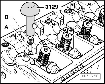
Installing

Note:

A plastic sleeve -A- is included with the new valve stem seals.

  • ‒ → So as not to damage new valve stem seals -B-, attach plastic sleeve -A- to valve stem.
  • ‒ Lubricate sealing lip of valve stem seal slightly.
  • ‒ Slip valve stem seal over plastic sleeve.
  • ‒ Press valve stem seal carefully onto valve guide using press-on tool 3129.
  • ‒ Detach plastic sleeve again.
 
A15-0445
  • ‒ → If valve keys are removed from assembly cartridge, they must first be placed in insertion tool VAS 5161/18.

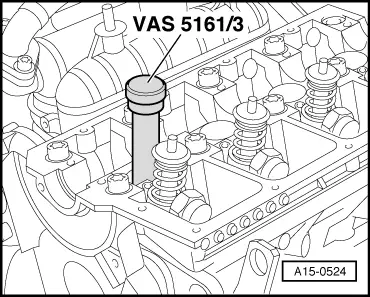
Note:

Large valve key diameter faces upwards.

  • ‒ Press assembly cartridge VAS 5161/15 from above onto insertion tool and insert into valve keys.

 
A15-0525
  • ‒ → Re-insert assembly cartridge VAS 5161/15 into guide bush VAS 5161/16.
  • ‒ Press down tool VAS 5161/2 and pull up knurled screw by twisting it in both directions, thus inserting the valve keys.
  • ‒ Release tool VAS 5161/2 with knurled screw still pulled.
  • ‒ Insert bucket tappets.
  • ‒ Fit camshaft => Page 15-64.

Notes:

  • ◆ Engine is not to be started for approx. 30 minutes after installing camshaft, so as to allow hydraulic valve lifters to settle (valves would otherwise strike piston).
  • ◆ After working on valve gear, carefully crank engine through at least 2 revolutions to ensure that no valves make contact on starting.

Tightening torques

Component

Nm

Glow plugs in cylinder head

15

Fuel filter holder to

M6

10

cylinder head/cylinder block

M7

15

M8

20

Reworking valve seats > < Checking hydraulic bucket tappets