audi Workshop Repair Guides

Audi Workshop Service and Repair Manuals

Attaching engine to engine stand > < Removing and installing engine
4-cylinder Diesel Direct Injection Engine (TDI), Mechanics
Removing and installing engine
Removing

Notes:

  • ◆ The engine is removed from the front without the gearbox.
  • ◆ Renew all cut and defective cable ties. Refit cable ties in the same position when installing the engine.
  • ◆ Catch drained off coolant in a clean container for re use or disposal.
  • ‒ Observe or obtain radio code on vehicles with coded radio.
  • ‒ Run windscreen wipers to vertical position.
 
N02-0130
  • ‒ Disconnect earthing strap at battery with ignition switched off.
  • ‒ Open the cover of the coolant expansion tank
  • ‒ Remove front bumper:

=> General body repairs; Repair group 63; Front bumper; Removing and installing front bumper

  • ‒ → Remove noise insulation -arrows-.
  • ‒ Place drip tray V.A.G 1306 below engine.
 
A10-0189
  • ‒ → Turn drain screw -arrow- on radiator anti clockwise. If necessary, fit drain hose on connection.

 
A19-0108
  • ‒ → To drain remaining coolant, remove screws -arrows-, detach connection, O-ring and thermostat.
 
A10-0347
  • ‒ → Pull off bottom coolant hose retaining clip -arrow- and remove coolant hose from radiator.

Vehicles with uprated cooling system:

  • ‒ Unplug connector -1- from radiator fan thermoswitch -F18/-F54 on radiator (bottom left) and move electrical wires clear.

Vehicles with automatic gearbox:

  • ‒ Place drip tray V.A.G 1306 underneath.
  • ‒ Detach ATF pipes at lock carrier

=> Automatic gearbox 01V; Repair group 37; Dismantling and assembling gearbox; Removing and installing ATF pipes

All models:

 
A10-0349
  • ‒ → Disconnect air intake hose -arrow- to charge air cooler at bottom left of lock carrier.
  • ‒ Disconnect air intake hose to turbocharger at bottom right of lock carrier.
 
A10-0352
  • ‒ Unbolt and remove air duct pipe leading to air cleaner on lock carrier.
  • ‒ → Disconnect hose -3- from air cleaner housing.
  • ‒ Unplug connector -1- at air mass meter.
  • ‒ Detach wiring harness from air cleaner housing -arrow-.
  • ‒ Remove air intake hose -4-.
  • ‒ Unscrew bolt -2-.
  • ‒ Detach air cleaner housing.

 
A10-0021
  • ‒ → Unplug connectors for headlights and headlight range control -arrows-.
  • ‒ Turn bulb holders for turn signals anti clockwise and remove from turn signal housing -left arrow-.
  • ‒ Pull off retaining clip for upper coolant hose and detach coolant hose from radiator.
 
A10-0350
  • ‒ → Remove screw and detach air charge hose together with left air duct pipe -arrows-.

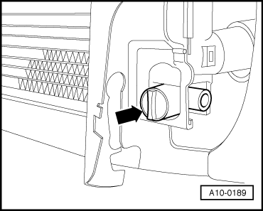
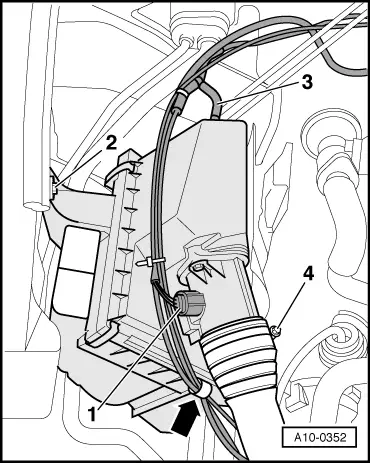
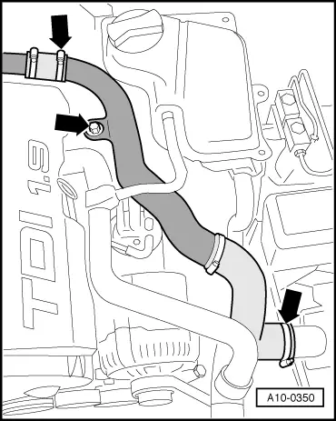
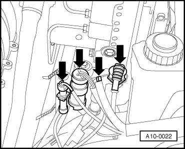
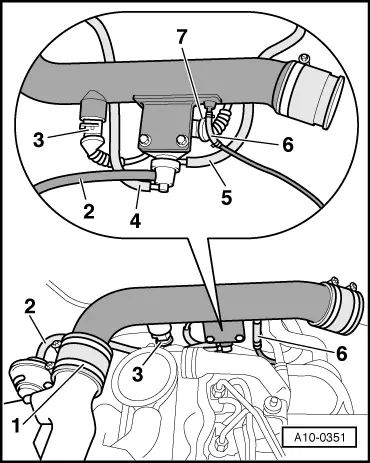
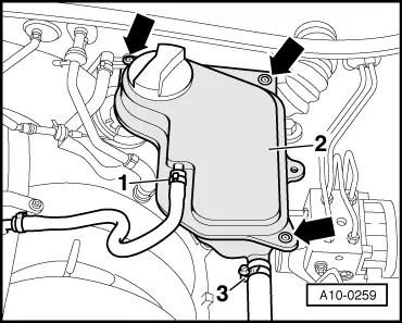
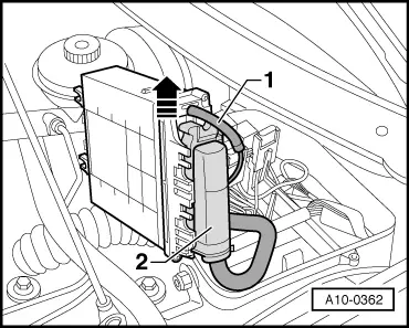
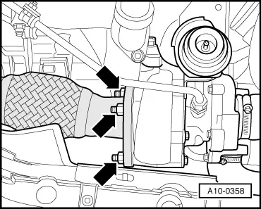
Note:

On vehicles 07.97 ▸ pipe has been discontinued. Only remove hose to charge air cooler.

  • ‒ Detach bonnet lock cable from lock carrier:

=> General body repairs; Repair group 55; Bonnet; Removing and installing bonnet lock cable

  • ‒ Detach cover from power steering fluid reservoir.

 
A10-0022
  • ‒ → Unplug connectors located in front of ABS unit -arrows- and move electrical wiring clear.
  • ‒ Unplug connector for anti theft alarm on lock carrier (top left) and move electrical wiring clear.
 
A10-0346
  • ‒ → Unplug connectors from both horns -1- and -2-, disengage electrical wiring from bracket -arrow- and move wiring clear.

Vehicles with air conditioner:

Important:
The air conditioner refrigerant circuit must not be opened.

Note:

To prevent damage to the condenser and refrigerant pipes/hoses, ensure that the pipes and hoses are not stretched, kinked or bent.

 
A19-0051
  • ‒ → Detach air cowls from radiator -4- (left and right).
  • ‒ Remove securing bolts -1- and -2- for condenser.
  • ‒ Pull connector -3- off low-pressure switch for air conditioner -F73.
  • ‒ Pull condenser up out of its bracket, pivot towards the side and secure to right-hand front wheel with wire.

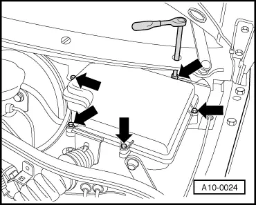
Note:

Protect wing panel from damage.

 
A10-0286
  • ‒ → Unclip green connector -arrow- for air conditioner magnetic clutch on lock carrier (bottom right). Unplug connector and move electrical wiring clear.
  • ‒ Unbolt lock carrier and place in a secure position.

 
A10-0034
  • ‒ → Remove engine cover panel -arrows-.
 
A10-0351

Vehicles ä 06.97:

  • ‒ → Remove rear air duct:
    • ‒ Unfasten hose clip -1-.
    • ‒ Detach hose -2-.
    • ‒ Disconnect connector -3-.
    • ‒ Detach hoses -4-, -5- and -6-.
    • ‒ Disconnect connector -7-.

Vehicles 07.97 ä:

 
A10-0409
  • ‒ → Remove rear air duct:
    • ‒ Detach hose -1-.
    • ‒ Unfasten hose clip -2-.
    • ‒ Disconnect connectors -3- and -4-.
    • ‒ Remove bolt -5-.
    • ‒ Detach hose -6-.
 
A21-0072

Vehicles with engine codes 1Z, AFF, AHU:

  • ‒ Pull connector -arrow- off solenoid valve for boost pressure control.

Vehicles with engine codes AFN, AHH:

 
A10-0353
  • ‒ → Pull off vacuum hose -2-.
  • ‒ Disconnect connector -3-, separate cable ties -arrow- and lay electrical wiring onto engine.
  • ‒ Remove bolts -5- and detach cover -4-.
  • ‒ Place solenoid valve for boost pressure control-1- to one side with hoses connected.

All models:

 
A10-0259
  • ‒ → Detach coolant hoses -1- and -3-.
  • ‒ Unbolt coolant expansion tank -2- (-arrows-).
  • ‒ Disconnect wiring to coolant shortage indicator switch -F66 at bottom of coolant expansion tank.

 
A10-0354
  • ‒ → Disconnect fuel supply line -1- and fuel return line -2- from filter cover and move to one side.
 
A10-0024
  • ‒ → Remove cover for electronics box (plenum chamber) -arrows-.

 
N28-0123
  • ‒ → Carefully lever off the retainer bar with a screwdriver -arrow-.
 
A10-0362
  • ‒ → Detach connector latches -arrow- and disconnect connector -2- of control unit.
  • ‒ Where fitted, disconnect hose -1- from control unit.

 
A10-0363
  • ‒ → Release latches -arrow- and pull off auxiliary relay carrier in electronics box upwards.
 
A10-0364
  • ‒ → Release both fuse holders on auxiliary relay carrier and pull off upwards.
  • ‒ With VAS 1978/8, release plug-in contact in plug-in board 2.

 
A10-0355
  • ‒ → Disconnect earth connection -1- on plenum chamber.
  • ‒ Disengage wiring harness -arrows- and move clear to one side.
 
A10-0366
  • ‒ → Pull off coolant hoses -1- and -3- to heating-system heat exchanger on engine.
  • ‒ Pull off vacuum hose -2- for brake servo
  • ‒ Unplug connector from speedometer sender -G22- on left of gearbox and move electrical wire clear.

Vehicles with manual gearbox

  • ‒ Unplug connector for reversing light switch on gearbox and move electrical wiring clear.

Vehicles with air conditioner:

Note:

 
A10-0013

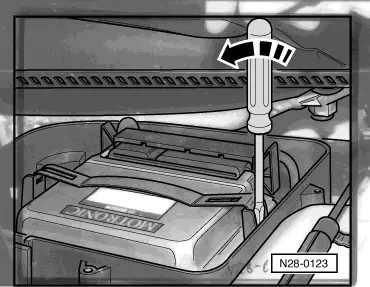
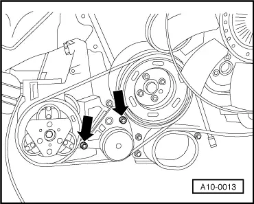
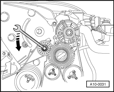
Before removing the ribbed belt, mark the direction of rotation with chalk or a felt pen. If the belt rotates in the wrong direction when it is refitted, this can cause breakage. Ensure that the belt is properly seated on the pulleys when installing.

  • ‒ → Loosen bolts securing ribbed belt tensioner for A/C compressor -arrows-. Slacken belt and remove.
  • ‒ Detach A/C compressor from bracket and secure to body with wire.
 
A10-0031
Important:
The air conditioner refrigerant circuit must not be opened.

All models:

  • ‒ → To slacken ribbed belt, turn tensioning element in direction of arrow.
  • ‒ Remove ribbed belt from alternator pulley.

 
A10-0356
  • ‒ → Counter hold pulley for viscous fan with 2-hole pin wrench 3212 and unscrew from bracket with 8 mm Allen key.
  • ‒ Remove ribbed V-belt.
  • ‒ Detach pulley from power steering vane pump. Use a drift to counter hold.
 
A10-0357
  • ‒ → Unbolt power steering vane pump -arrow-, move clear to one side and tie in place. Do not open hydraulic connections.
  • ‒ Unbolt cable clamp for positive cable to starter from engine (right side), below exhaust manifold.

 
A10-0358
  • ‒ → Unscrew turbocharger/catalytic converter bolts -arrows-.
  • ‒ Release front clamps for exhaust system.
  • ‒ Push clamp towards the rear and separate exhaust pipe.
  • ‒ Pull front exhaust pipe with catalytic converter off turbocharger.

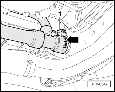
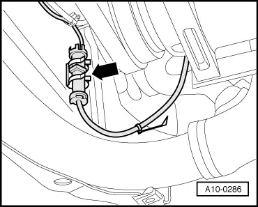
Note:

The isolating element in exhaust system must not be bent more than 10°to avoid damage.

 
A10-0359
  • ‒ → Unbolt earth wire from engine support (right side) -1-.
  • ‒ If fitted, remove bracket -2- for turbocharger -arrows-.

 
A10-0360
  • ‒ → Detach electrical wires -1- and -32- from starter, remove insulator from positive connection on starter.
  • ‒ Unbolt cable clamp -3-.
  • ‒ Unbolt starter from gearbox and remove.
 
A10-0190

Vehicles with automatic gearbox:

  • ‒ → Use 15 mm wrench socket Matra V/175 to screw out 3 nuts of torque converter in opening in removed starter (give crankshaft 1/3 of a turn in each case).

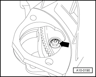
Note:

When loosening torque converter bolts, counterhold crankshaft by applying spanner to central bolt on vibration damper.

All models:

  • ‒ Loosen nuts a few turns on left and right engine mountings (top).
 
A10-0088
  • ‒ → Mark positions of mountings -1- and locating sleeves -2- on left and right engine mountings (bottom).

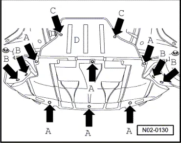
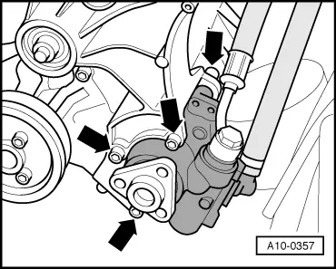
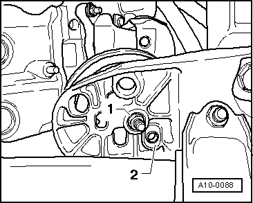
Note:

Different mounting holes are provided for the different engine versions.
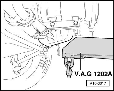
  • ‒ Remove bottom nuts -1- on left and right engine mountings.
 
A10-0017
  • ‒ → Lift engine and gearbox slightly on bracket for torque reaction support using workshop crane V.A.G 1202 A.
Important:
Ensure that components are supported safely - accident risk.

Note:

Ensure that wiring and other connections are not damaged at top of bulkhead.

  • ‒ Unscrew engine/gearbox securing bolts accessible from below.

Vehicles with automatic gearbox:

  • ‒ Unbolt bracket for ATF pipes from left of engine.

All models:

  • ‒ Lower engine back down again.
  • ‒ Refit nuts loosely to engine mounting studs.
  • ‒ Remove nuts on top engine mountings.
 
A10-0224
  • ‒ → Set up support bar 10-222 A on wing panel flanges. Spindle is at front.
  • ‒ Engage gearbox support 3147 in bolthole in bell housing on gearbox.
  • ‒ Connect gearbox support 3147 to support bar 10-222 A using extension 2024 A/1 and bar 2024 A/2 (secure bolt with nut and washer).

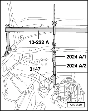
Note:

Shown in illustration with engine removed.

  • ‒ Unscrew upper engine/gearbox securing bolts. Leave one bolt in place (hand tight).
 
A10-0361
  • ‒ → Attach lifting device 2024 A to engine and to workshop crane V.A.G 1202 A.

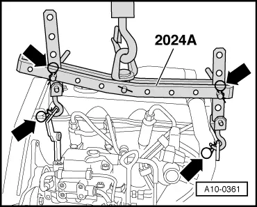
Note:

To balance the centre of gravity of the engine, position the hook attachments as shown in the illustration.

Important:
The hooks and locating pins of the lifting tackle must be secured with locking pins -arrows in illustration.
  • ‒ Remove the last securing bolt.

Note:

Check that all hoses and other connections between engine and body have been detached.

  • ‒ Lift engine over studs of engine mounts.
  • ‒ Tighten spindle of support bar 10-222 A.
  • ‒ Guide engine out of engine compartment from the front.

Vehicles with automatic gearbox:

  • ‒ Secure torque converter in gearbox to prevent it falling out.

Attaching engine to engine stand > < Removing and installing engine