audi Workshop Repair Guides

Audi Workshop Service and Repair Manuals

Valve dimensions > < Renewing valve stem oil seals with cylinder head installed
Renewing valve stem oil seals with cylinder head removed
   
Renewing valve stem oil seals with cylinder head removed
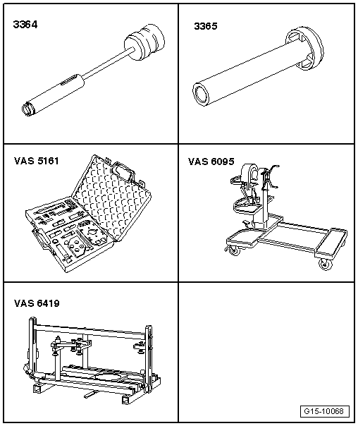
Special tools and workshop equipment required
t  Valve stem seal puller -3364-
t  Valve stem seal fitting tool -3365-
t  Removal and installation device for valve cotters -VAS 5161-
t  Engine and gearbox support -VAS 6095-
t  Cylinder head tensioning device -VAS 6419-

Procedure
–  Remove camshafts and camshaft adjuster → Chapter.
–  Mark allocation of bucket tappets for re-installation.
–  Remove the bucket tappets from the guides and put them down with the contact surface downwards.
   
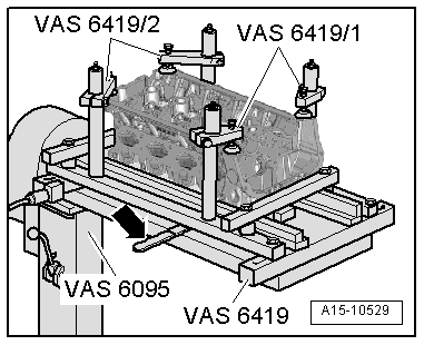
–  Attach tensioning device -VAS 6419- to engine and gearbox support -VAS 6095-.
–  Secure cylinder head in tensioning device -VAS 6419- as illustrated.
–  Connect compressed air line to tensioning device -VAS 6419-.
–  Using lever -arrow-, slide air pad under combustion chamber where valve stem oil seal is to be removed.
–  Apply just enough compressed air to bring air pad into contact with valve heads.
  A15-10529
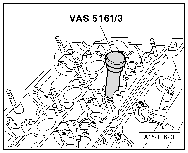
–  Apply drift -VAS 5161/3- to valve spring plate and use plastic-headed hammer to release sticking valve cotters.
  A15-10693
Exhaust side:
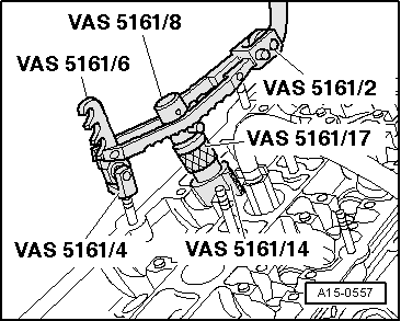
–  Screw snap-in device -VAS 5161/6- with engaging fork -VAS 5161/4- onto stud on cylinder head.
–  Push guide bush -VAS 5161/14- as far as it will go into bucket tappet guide on valve to be removed.
l  Installation position: knurled surfaces face perpendicular to direction of travel.
–  Slide knurled spacer ring -VAS 5161/17- onto assembly cartridge -VAS 5161/8-.
–  Insert assembly cartridge in guide bush.
–  Attach pressure fork -VAS 5161/2- to snap-in device -VAS 5161/6- and push assembly cartridge down.
–  At the same time, turn knurled screw of assembly cartridge clockwise until tips engage in valve cotters.
–  Move knurled screw back and forth slightly; the valve cotters are thus forced apart and taken up by the assembly cartridge.
–  Release pressure fork.
–  Take off assembly cartridge with knurled spacer ring.
–  Remove guide bush, valve spring plate and valve spring.
  A15-0557
Inlet side:
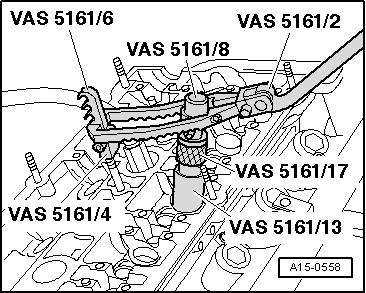
–  Screw snap-in device -VAS 5161/6- with engaging fork -VAS 5161/4- onto stud on cylinder head.
–  Push guide bush -VAS 5161/13- as far as it will go into bucket tappet guide on valve to be removed.
l  Installation position: knurled surfaces face perpendicular to direction of travel.
–  Slide knurled spacer ring -VAS 5161/17- onto assembly cartridge -VAS 5161/8-.
–  Insert assembly cartridge in guide bush.
–  Attach pressure fork -VAS 5161/2- to snap-in device -VAS 5161/6- and push assembly cartridge down.
–  At the same time, turn knurled screw of assembly cartridge clockwise until tips engage in valve cotters.
–  Move knurled screw back and forth slightly; the valve cotters are thus forced apart and taken up by the assembly cartridge.
–  Release pressure fork.
–  Take off assembly cartridge with knurled spacer ring.
–  Remove guide bush, valve spring plate and valve spring.
  A15-0558
Continuation for both sides:
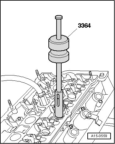
–  Pull off valve stem oil seal with valve stem seal puller -3364-.
  A15-0559
  Caution
Make sure valve stem oil seals are not damaged when installing.
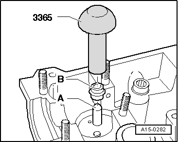
New valve stem oil seals -B- are supplied with plastic sleeve; fit plastic sleeve -A- onto valve stem.
–  Lightly oil sealing lip of valve stem oil seal.
–  Slide valve stem oil seal onto plastic sleeve.
–  Carefully press valve stem oil seal onto valve guide using valve stem seal fitting tool -3365-.
–  Remove plastic sleeve.
  A15-0282
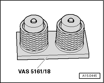
–  If valve cotters have been removed from assembly cartridge, they need to be put into insertion device for valve cotters -VAS 5161/18- first.
l  Larger diameter of valve cotters faces upwards.
–  Press assembly cartridge -VAS 5161/8- onto insertion device from above and take up valve cotters.
  A15-0445
–  Insert assembly cartridge in guide bush -VAS 5161/13- or -VAS 5161/14-.
–  Press down pressure fork and pull knurled screw upwards while turning screw in both directions - this will insert the valve cotters.
–  Release the pressure fork with knurled screw still in pulled position.
–  Repeat procedure for each valve.
Assembling
Installation is carried out in the reverse order; note the following:
–  Install bucket tappets.
–  Install camshafts and camshaft adjuster → Chapter.
  A15-0557

Valve dimensions > < Renewing valve stem oil seals with cylinder head installed