
A4 Mk1
| Valve gear - exploded view |
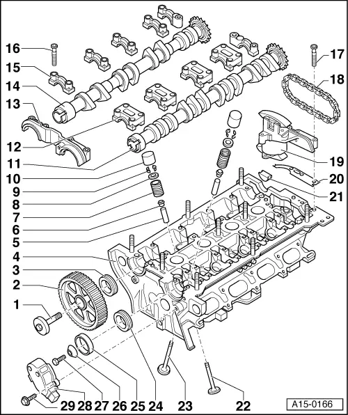
| 1 - | Bolt |
| q | Use counterhold tool -3036- when loosening and tightening |
| q | 65 Nm |
| 2 - | Camshaft sprocket |
| q | For exhaust camshaft |
| q | Note installation position: The camshaft sprocket is installed with the smaller web facing out and the “TDC” marking is visible from the front → Anchor |
| 3 - | Exhaust camshaft oil seal |
| q | Renewing → Chapter |
| 4 - | Cylinder head |
| q | See note → Chapter |
| q | Checking valve guides → Chapter |
| q | Machining valve seats → Chapter |
| q | Dowel sleeves for bearing caps must be positioned in cylinder head |
| 5 - | Valve guide |
| q | Checking → Chapter |
| 6 - | Valve stem oil seal |
| q | Renewing with cylinder head installed → Chapter |
| q | Renewing with cylinder head removed → Chapter |
| 7 - | Valve spring |
| q | Removing and installing → Chapter or → Chapter |
| 8 - | Valve spring plate |
| 9 - | Valve cotters |
| 10 - | Hydraulic bucket tappet |
| q | Checking → Chapter |
| q | Removing and installing → Chapter |
| q | Do not interchange |
| q | Place down with contact surface facing downwards |
| q | Before installing, check camshaft axial clearance → Chapter |
| q | Lubricate contact surface |
| 11 - | Inlet camshaft |
| q | Removing and installing → Chapter |
| q | Measuring axial clearance → Chapter |
| q | Check radial clearance with Plastigage (bucket tappets removed) |
| q | Radial clearance: wear limit: 0.1 mm |
| q | Runout: max. 0.01 mm |
| 12 - | Bearing cap for inlet camshaft |
| q | Must be positioned on dowel sleeves |
| q | Dowel sleeves must be positioned in cylinder head |
| q | Note installation position |
| q | Installation sequence → Anchor |
| 13 - | Double bearing cap |
| q | Must be positioned on dowel sleeves |
| q | Dowel sleeves must be positioned in cylinder head |
| q | Before installing, apply small quantity of sealant to sealing surface |
| q | Applying sealant to sealing points between double bearing cap and cylinder head |
| 14 - | Exhaust camshaft |
| q | Removing and installing → Chapter |
| q | Measuring axial clearance → Chapter |
| q | Check radial clearance with Plastigage (bucket tappets removed) |
| q | Radial clearance: wear limit: 0.1 mm |
| q | Runout: max. 0.01 mm |
| 15 - | Bearing cap for exhaust camshaft |
| q | Must be positioned on dowel sleeves |
| q | Dowel sleeves must be positioned in cylinder head |
| q | Note installation position |
| q | Installation sequence → Anchor |
| 16 - | Bolt |
| q | 10 Nm |
| 17 - | Bolt |
| q | 10 Nm |
| 18 - | Drive chain |
| q | Check for wear |
| q | Removing and installing → Chapter „Removing and installing camshafts and hydraulic chain tensioner“ |
| q | Mark installation position prior to removal if old drive chain is to be reused → Anchor |
| 19 - | Hydraulic chain tensioner |
| q | Before removing, lock in position with chain tensioner retainer -3366- |
| q | Removing and installing → Chapter |
| q | Apply sealant to transition points between hydraulic chain tensioner and cylinder head |
| 20 - | Rubber/metal gasket |
| q | Renew |
| 21 - | Seal |
| q | Renew |
| 22 - | Exhaust valve |
| q | With sodium filling |
| q | Note safety requirements when disposing of valves with sodium filling → Chapter |
| q | Must not be machined; only grinding-in is permissible |
| q | Valve dimensions → Chapter |
| q | Checking valve guides → Chapter |
| q | Machining valve seats → Chapter |
| 23 - | Inlet valve |
| q | Must not be machined; only grinding-in is permissible |
| q | Valve dimensions → Chapter |
| q | Checking valve guides → Chapter |
| q | Machining valve seats → Chapter |
| 24 - | Inlet camshaft oil seal |
| q | Renewing → Chapter |
| 25 - | Rotor for Hall sender |
| q | Note installation position: insert lug into notch on camshaft |
| 26 - | Washer |
| q | With taper |
| q | Note installation position |
| 27 - | Bolt |
| q | 25 Nm |
| 28 - | Hall sender -G40- housing |
| 29 - | Bolt |
| q | 10 Nm |