audi Workshop Repair Guides

Audi Workshop Service and Repair Manuals

Removing and installing, checking coolant thermostat > < Removing and installing coolant pump and coolant thermostat
4-Cylinder engine (2-valve), Mechanics
Removing and installing parts of cooling system
Removing and installing coolant pump

Note:

The coolant pump is bolted to the bracket for the alternator, vane pump and viscous fan.

  • ● Lock carrier must be in service position .

Removing

  • ‒ Obtain radio code on vehicles with coded radio.
  • ‒ With ignition switched off disconnect battery earth strap.
  • ‒ Remove ribbed belt => Page 13-17.
  • ‒ Remove viscous fan (with belt pulley) => Fig. 13-16
 
A10-0091
  • ‒ Remove V-belt => Page 13-20.

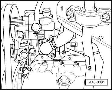
Note:

Ribbed belt for A/C compressor and torque reaction support need not be removed.

  • ‒ Draining cooling system=> Page 19-4
  • ‒ → Disconnect coolant hoses -1- and -2- from coolant pump and coolant thermostat housing.
  • ‒ Unbolt front support at bracket for alternator, vane pump and viscous fan.
  • ‒ Detach radiator hose at upper coolant pipe.
  • ‒ Unscrew alternator securing bolts.
  • ‒ Remove alternator from the front.
  • ‒ Disconnect wiring from alternator after removal.
 
A19-0058
  • ‒ Unbolt and remove both front support brackets for intake manifold.
  • ‒ → Unbolt bracket for alternator, vane pump and viscous fan -bolts 1 ... 6-.
  • ‒ Move bracket for alternator, vane pump and viscous fan clear to the left and tie in place with wire.

Note:

The vane pump does not have to be removed.

 
A19-0070
  • ‒ → Unbolt coolant pump housing from lower toothed belt guard -arrow-.
  • ‒ Remove coolant pump.

 
A19-0025
  • ‒ → Unbolt bearing housing -1- from pump housing -4-.

Installing

Installation is carried out in the reverse order, when doing this note the following:

  • ‒ Clean sealing surfaces on both sections of housing.
  • ‒ Renew gasket and O-ring.
 
A19-0058
  • ‒ Insert hammer-head bolt in drilling in coolant pump.
  • ‒ → Locate bracket for alternator, vane pump and viscous fan on cylinder block together with coolant pump and tighten the bolts in the sequence indicated below:
  •     1 -    Bolt M8 x 70
  •     2 -    Bolt M8 x 110
  •     3 -    Bolt M8 x 50
  •     4 -    Bolt M8 x 90
  •     5 -    Bolt M8 x 70
  •     6 -    Bolt M8 x 100
  • ‒ Install viscous fan => Fig. 13-16.
  • ‒ Install ribbed belt .
  • ‒ Install V-belt .
  • ‒ Fill up with coolant=> Page 19-6.
  • ‒ After connecting battery terminals, program in the radio anti-theft code.

=> Radio operating instructions

  • ‒ Close windows fully using electric window switches.
  • ‒ Then operate all electric window switches again for at least one second in the "close" direction to activate the automatic one-touch function.
  • ‒ Set clock to correct time.

Tightening torques

Component

Nm

Bearing housing to pump housing

10

Pump housing to toothed belt guard

10

Bracket for alternator, vane pump and viscous fan to cylinder block


25

Vehicles with air conditioner: strut for torque reaction support / bracket for alternator, vane pump and viscous fan

to torque reaction
support

25

to bracket

20

Support brackets for intake manifold

to intake manifold

20

to bracket

20

Alternator to bracket for alternator,
vane pump and viscous fan

M8

25

M10

40

Belt pulley to coolant pump

25

Viscous fan to viscous fan bearing

45

Removing and installing, checking coolant thermostat > < Removing and installing coolant pump and coolant thermostat