audi Workshop Repair Guides

Audi Workshop Service and Repair Manuals

Connecting remote control > < Removing and installing fuel gauge sender
4-Cylinder engine (2-valve), Mechanics
Removing and installing parts of fuel supply system
Removing and installing fuel delivery unit

Observe notes .

Observe safety precautions=> Page 20-2

Observe rules for cleanliness => Page 20-3

Special tools, testers and auxiliary items

  • ◆ Ring nut spanner 3217
  • ◆ Fuel pump spanner 3307
  • ◆ Hose clamp pliers V.A.G 1275
  • ◆ Fuel extractor V.A.G 1433 A

Removing

Notes:

  • ◆ The fuel tank must not be more than 1/3 full.
  • ◆ If necessary, draw off fuel with fuel extractor V.A.G 1433 A.
  • ‒ Obtain radio code on vehicles with coded radio.
  • ‒ With ignition switched off disconnect battery earth strap.
 
A20-0190
  • ‒ Remove luggage compartment trim.
  • ‒ Unbolt cover for flange on fuel tank under floor trim in luggage compartment.
  • ‒ → Mark the supply pipe -2- and return pipe -3-, then pull pipes off flange.
  • ‒ Release 4-pin connector -1- and unplug.

 
V20-1026
  • ‒ → Remove union nut with spanner 3217.
  • ‒ Remove flange and seal out of opening in fuel tank.
  • ‒ Unplug connector for fuel gauge sender on inside of flange.
  • ‒ Pull fuel return pipe off inside of fuel delivery unit flange (press release tabs).
 
V20-1101
  • ‒ → Insert fuel pump spanner 3307 through opening in fuel tank and apply spanner to inner section of baffle housing.
  • ‒ Using spanner 3307 turn inner section of baffle housing anti-clockwise as far as it will go (approx. 15°), and take out fuel pump with inner section of baffle housing.

Pre-assembling flange and inner section of baffle housing

  • ‒ If flange and delivery unit have been separated, pre-assemble components before installing => Page 20-15.
 
A20-0194
    • ‒ → Angle between flange and inner section of baffle housing: 10°
  • Compress clamps for supply pipe (between pump and flange) using hose clamp pliers V.A.G 1275.
  • Connect electrical wires onto fuel pump
    (M4: 1.5 Nm; M5: 2 Nm)

Note:

Fit a toothed washer under each nut.

  • ‒ Secure the electrical wires using a fuel-resistant cable tie.
 
A20-0112

Installing

  • ‒ Insert inner section of baffle housing, supply hose and flange in fuel tank.
  • ‒ → Fit inner section of baffle housing into outer section of baffle housing (in tank) so that notch -1- on inner section of housing is aligned with marking -2- on outer section of housing.
    • ‒ It should be possible to push down inner section of baffle housing noticeably.

Note:

 
V20-1101

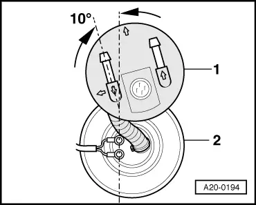
Baffle housing is shown without fuel tank for a clearer illustration.

  • ‒ → Apply fuel pump spanner 3307 and turn pump together with inner section of baffle housing clockwise as far as it will go (approx. 15°). Notch -1- will then be aligned with marking -3- (bayonet fitting) => Fig. A20-0112.
 
A20-0219
  • ‒ → When installing, turn flange in an anti-clockwise direction, as indicated in illustration.
  • ‒ Connect return pipe on inside of flange.

Note:

Lubricate O-rings with fuel or other lubricant.

  • ‒ Wrap wire for fuel gauge sender once round return pipe (in tank) and connect to flange.

Note:

Lubricate the flange seal with fuel before fitting.

 
A20-0119
  • ‒ → Insert flange in tank; note correct installation position:
    • ‒ Marking onflange must coincide with marking on fuel tank -arrows-.
    • ‒ Installation position for vehicles with front-wheel drive:
      -arrow 2- must be aligned with -arrow 3-.

Note:

-Arrow 1- is for vehicles with four-wheel drive (can be ignored).

 
V20-1026
  • ‒ → Tighten union nut with spanner 3217.

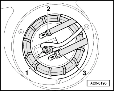
Note:

The pipe retainer -Item 20-16 must be held in position when tightening the union nut.

  • ‒ Connect pipes and plug in the connector.

Note:

Ensure that fuel pipes are fitted securely.

    • ‒ Blue = return pipe
    • ‒ Black = supply pipe

Tightening torque

Component

Nm

Union nut for flange

60

Connecting remote control > < Removing and installing fuel gauge sender