audi Workshop Repair Guides

Audi Workshop Service and Repair Manuals

Enginecrankshaft group, pistons > < Securing engine to assembly stand
Installing engine
Installing engine
  Note
t  Renew self-locking nuts and bolts when performing assembly work.
t  Renew bolts which are tightened to a specified angle as well as oil seals and gaskets.
t  Secure all hose connections with the correct type of hose clips (same as original equipment) → Parts catalogue.
t  Fit all heat insulation sleeves in the original position when installing.
t  Fit all cable ties in the original positions when installing.
–  Check clutch release bearing for wear; renew if necessary.
–  Clean input shaft splines and (in the case of used clutch plates) the hub splines. Remove corrosion and apply only a very thin coating of grease for clutch plate splines -G 000 100- to the splines. Do not lubricate guide sleeve.
–  Check that clutch plate is correctly centred.
–  A needle bearing must be fitted in the crankshaft. If necessary, install needle bearing → Chapter.
–  Check whether dowel sleeves for centring the engine/gearbox assembly are fitted in the cylinder block; install if necessary.
   
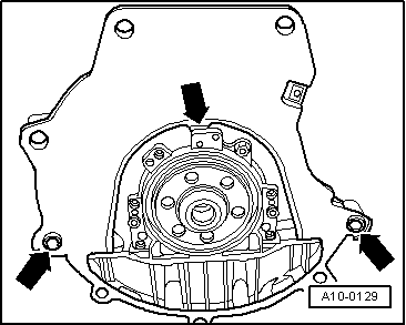
–  Ensure that the intermediate plate is engaged on the sealing flange and pushed onto the dowel sleeves -arrows-.
–  Attach engine to gearbox and screw in one bolt finger-tight.
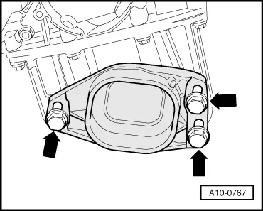
–  Install engine mounting (left-side).
–  Release spindle of support bracket -10-222 A-.
–  Lower engine, inserting studs of engine mountings into consoles for engine mountings as you do so.
  Note
t  Tightening torques apply only to lightly greased, oiled, phosphated or black-finished nuts and bolts.
t  Additional lubricant such as engine oil or gearbox oil may be used, but do not use lubricant containing graphite.
t  Do not use degreased parts.
t  Tolerance for tightening torques ± 15 %.
  A10-0129
Securing engine to gearbox
  A37-0075
ItemBoltNm
1, 3, 4M12x6765
2, 6M12x9065
5, 11M12x11065
7 … 10M10x4545
ADowel sleeves for centralising
l  1) Renew bolts.

Remaining installation steps are carried out in reverse sequence; note the following:
–  Install engine mountings free of stress. To do so, shake engine before tightening engine mountings.
–  Install exhaust system and align free of stress → Chapter.
–  Install air conditioner compressor → Rep. Gr.87.
–  Install power steering pump → Rep. Gr.48.
–  Install poly V-belt → Chapter.
   
–  Install lock carrier with attachments → Rep. Gr.50.
–  Allow stop for torque reaction support to rest on rubber buffer for torque reaction support under its own weight and tighten bolts -arrows-.
–  Install front bumper → Rep. Gr.63.
–  Electrical connections and routing → Current flow diagrams, Electrical fault finding and Fitting locations.
–  Observe notes on procedures required after connecting battery → Rep. Gr.27.
  Caution
Do not use a battery charger to boost starting. There is danger of damaging the vehicle's control units.
–  Check oil level → Chapter.
–  Check fluid level of power steering → Rep. Gr.48.
–  Fill cooling system → Anchor.
  Note
t  Drained-off coolant may only be used again if the original cylinder head and cylinder block are re-installed.
t  Contaminated or dirty coolant must not be used again.
–  Check headlight adjustment → Booklet802.
Tightening torques
  Note
t  Tightening torques apply only to lightly greased, oiled, phosphated or black-finished nuts and bolts.
t  Additional lubricant such as engine oil or gearbox oil may be used, but do not use lubricant containing graphite.
t  Do not use degreased parts.
t  Tolerance for tightening torques ± 15 %.
  A10-0767
ComponentNm
Bolts/nutsM610
 M820
 M1045
 M1265
Except for the following: 
Engine mounting to engine console23
Engine mounting to engine support23
Terminal B+ to starter16
Drive shaft heat shield to gearbox23
Fuel line to fuel rail22
Stop for torque reaction support to sump28
Hose clips for coolant hoses2


Enginecrankshaft group, pistons > < Securing engine to assembly stand