audi Workshop Repair Guides

Audi Workshop Service and Repair Manuals

Piston and cylinder dimensions > < Crankshaft dimensions
4-Cylinder engine (5-valve), Mechanics
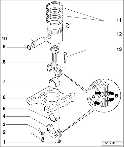
Dismantling and assembling pistons and conrods
 
A13-0109
  • 30 Nm +1/4turn (90°) further
    • ◆ Renew conrod bolts (Item 13)
    • ◆ Oil threads and contact surface
    • ◆ To measure radial clearance tighten to 30 Nm but not further
  • Pressure relief valve, 27 Nm
    • ◆ opens at:
      2.5 ... 3.2 bar
  • Oil spray jet
    • ◆ For piston cooling
 
A13-0109
  • Conrod bearing cap
    • ◆ Mark cylinder number -B-
    • ◆ Installation position:
      Marking -A- faces towards pulley end
  • Bearing shell
    • ◆ Note installation position
    • ◆ Do not interchange used bearing shells (mark)
    • ◆ Ensure retaining lugs fit tightly in recesses
    • ◆ Axial clearance
      New: 0.10...0.35 mm
      Wear limit: 0.40 mm
    • ◆ Check radial clearance with Plastigage:
      New: 0.01...0.05 mm
      Wear limit: 0.12 mm
      Do not rotate crankshaft when checking radial clearance
    • ◆ To measure radial clearance, tighten nuts -Item 1- to 30 Nm but do not turn further
 
A13-0109
  • Cylinder block
    • ◆ Checking cylinder bores
      =>Fig. 4
    • ◆ Piston and cylinder dimensions
      =>Page 13-78
  • Bearing shell
    • ◆ With oil drilling for piston pin lubrication
    • ◆ Note installation position
    • ◆ Do not interchange used bearing shells (mark)
    • ◆ Axial clearance
      New: 0.10...0.35 mm
      Wear limit: 0.40 mm
    • ◆ Check radial clearance with Plastigage:
      New: 0.01...0.05 mm
      Wear limit: 0.12 mm
      Do not rotate crankshaft when checking radial clearance
    • ◆ To measure radial clearance, tighten nuts -Item 1- to 30 Nm but do not turn further
 
A13-0109
  • Conrod
    • ◆ Only renew as a set
    • ◆ Mark cylinder number -B-
    • ◆ Installation position:
      Marking -A- faces towards pulley end
    • ◆ With oil drilling for piston pin lubrication
  • Circlip
  • Piston pin
    • ◆ If difficult to move, heat piston to approx. 60 °C
    • ◆ Remove and install with VW 222a
 
A13-0109
  • Piston ring
    • ◆ Offset gaps by 120 °
    • ◆ Remove and install with piston ring pliers
    • ◆ "TOP" must face towards piston crown
    • ◆ Checking ring gap=> Fig. 1
    • ◆ Checking ring to groove clearance
      => Fig. 2
  • Piston
    • ◆ Checking => Fig. 3
    • ◆ Mark installation position and cylinder number
    • ◆ Arrow on piston crown points to pulley end
    • ◆ Install using piston ring clamp
  • Conrod bolt
    • ◆ Renew
 
V13-0016

→ Fig. 1    Checking piston ring gap

  • ‒ Push ring squarely from above down to approx. 15 mm from bottom end of cylinder.

Piston ring
Dimensions in mm

New

Wear limit

1st compression ring

0.20...0.40

0.8

2nd compression ring

0.20...0.40

0.8

Oil scraper ring

0.25...0.50

0.8

 
V13-0687

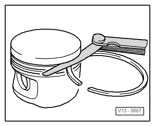
→ Fig. 2    Checking ring to groove clearance

  • ‒ Clean groove before checking clearance.

Piston ring
Dimensions in mm

New

Wear limit

1st compression ring

0.06...0.09

0.20

2nd compression ring

0.05...0.08

0.20

Oil scraper ring

0.03...0.06

0.15

 
V13-0010

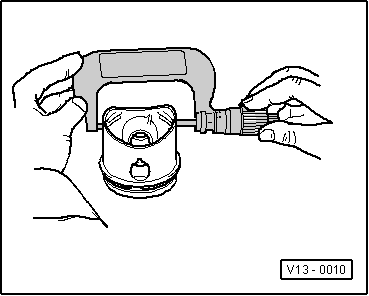
→ Fig. 3    Checking piston

  • ‒ Measure pistons approx. 10 mm from lower edge of skirt, at 90° to the piston pin axis.
    • ‒ Deviation from nominal dimension
      not more than 0.04 mm

 
V13-0280

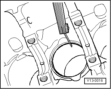
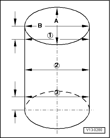
→ Fig. 4    Checking cylinder bores

  • ‒ Use internal dial gauge 50 ... 100 mm.
  • ‒ Take measurements at 3 positions in both lateral -A- and longitudinal -B- directions.
    • ‒ Deviation from nominal dimension
      not more than 0.08 mm

Piston and cylinder dimensions > < Crankshaft dimensions