audi Workshop Repair Guides

Audi Workshop Service and Repair Manuals

Removing > < Rules for cleanliness
4-Cylinder engine (5-valve), Mechanics
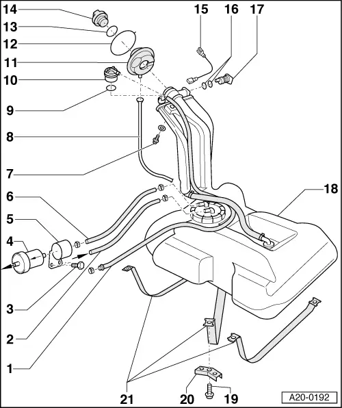
Removing and installing parts of fuel supply system
Removing and installing fuel tank with its attachments and fuel filter (vehicles with front-wheel drive)
 
A20-0192
  • Breather pipe
    • ◆ To activated charcoal filter
      , Item 2
  • Return pipe
    • ◆ From fuel manifold
    • ◆ Note direction of arrow on flange
  • 20 Nm
  • Fuel filter
    • ◆ Installation position: Arrow points in through-flow direction
 
A20-0192
  • Retaining clip
    • ◆ For fuel filter
  • Supply pipe
    • ◆ To fuel manifold
    • ◆ Note direction of arrow on flange
  • 25 Nm
  • Overflow hose
  • O ring
    • ◆ Renew
  • Gravity valve
    • ◆ Position => Fig. 1
    • ◆ To remove valve unclip upwards out of filler neck
    • ◆ Check valve for through-flow
      valve vertical: open,
      valve tilted 45 °: closed
 
A20-0192
  • Rubber cup
  • Retaining ring
  • Seal
    • ◆ Renew if damaged
  • Cap
  • Earth connection
    • ◆ Position => Fig. 1
    • ◆ Ensure that connector is seated properly on metal ring of filler neck
    • ◆ Secure the contact tab of wire with bolt for fuel filler neck -Item 20-5
    • ◆ After installation, use an ohmmeter to check the electrical connection between the metal ring on the fuel filler neck and a bare metal part on the body
      Specification: approx. 0 ω.
 
A20-0192
  • O rings
    • ◆ Renew
  • Vent valve
    • ◆ Position => Fig. 1
    • ◆ Checking =>Fig.2
  • Fuel tank
    • ◆ Removing and installing
  • 25 Nm
    • ◆ Note tightening sequence
      => Page 20-13
  • Bracket
    • ◆ For securing straps
  • Securing straps
    • ◆ Removing and installing
    • ◆ Note different lengths
    • ◆ Note correct position
 
A20-0188

→ Fig.1    Position of gravity valve, vent valve and earth connection

  •     1 -    Earth connection
  •     2 -    Gravity valve
  •     3 -    Filler neck
  •     4 -    Vent valve
  • ‒ Route earth connection as shown in illustration.
  • ‒ Ensure that plug connector for earth connection is properly seated on metal ring on fuel filler neck.
 
A20-0115
  • ‒ → Secure the contact tab -1- of wire with bolt -2- for fuel filler neck.
  • ‒ After installation, use an ohmmeter to check the electrical connection between the metal ring on the fuel filler neck and a bare metal part on the body.
    • ‒ Specification: approx. 0 ω
 
V20-1040

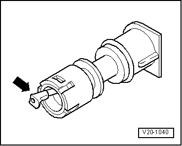
→ Fig. 2    Checking vent valve

    • ‒ Lever in released position: valve closed
    • ‒ Lever pressed in direction of arrow: valve open

Removing > < Rules for cleanliness