
A4 Mk1
 Note
Note
|
|
|
|
|
|
|
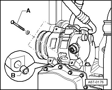
 Caution
|
|
|
|
|
|
|
|
|
|
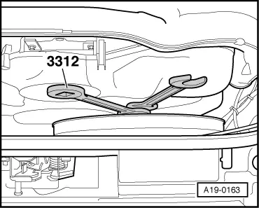
| Tightening torque for viscous fan | Nm |
| Torque wrench -V.A.G 1331- together with open-end spanner -3312- | 37 |
| Torque wrench -V.A.G 1331- without open-end spanner -3312- | 70 |
|
Note
Note
Note
|
|
|
|
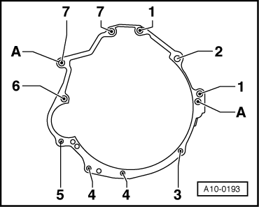
| Item | Bolt | Nm | ||
| 1 | M12x80 | 65 | ||
| 2 | M12x90 | 65 | ||
| 3 | M10x50 1) | 45 | ||
| 4 | M10x45 | 45 | ||
| 5 | M10x135 | 65 | ||
| 6 | M12x110 | 65 | ||
| 7 | M12x67 | 65 | ||
| A | Dowel sleeves for centralising | |||
| ||||
|
|
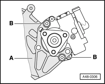
| Item | Bolt | Nm |
| 1 | M12x80 | 65 |
| 2 | M12x90 | 65 |
| 3 | M10x60 | 45 |
| 4 | M10x45 | 45 |
| 5 | M10x80 | 65 |
| 6 | M12x110 | 65 |
| 7 | M12x67 | 65 |
| A | Dowel sleeves for centralising | |
| Component | Nm | |
| Bolts/nuts | M6 | 10 |
| M8 | 20 | |
| M10 | 45 | |
| M12 | 65 | |
| Except for the following: | ||
| Engine support to cylinder block | 45 | |
| Air cleaner housing to body | 10 | |
| Tensioning roller for poly V-belt for A/C compressor to bracket | 22 | |
| Front exhaust pipe to connection for turbocharger | 25 | |
| Heat shield to turbocharger | 10 | |
| Support for intermediate flange to intermediate flange | 22 | |
| Drain plug to coolant drain pipe | 10 | |
| Stop for torque reaction support to lock carrier | 25 | |
| Drive plate to torque converter M10x1 | 85 | |
| Air conditioner compressor to bracket | 22 | |
| Power steering pump to bracket for power steering pump and oil cooler | 22 | |
| Underbody cross member to body | 20 | |
| Poly V-belt pulley to power steering pump | 22 | |
| Engine mounting to subframe | 25 | |