audi Workshop Repair Guides

Audi Workshop Service and Repair Manuals

Installing sump (top section) - engines with moulded gasket > < Removing and installing oil pump
Removing sump (top section)
Special tools and workshop equipment required
   
t  Support bracket -10 - 222 A-
  W00-0225
t  Lifting tackle -2024 A-
  W00-0224
t  Workshop hoist -VAS 6100-
  W00-1214
t  
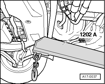
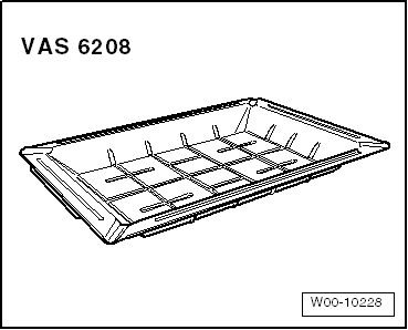
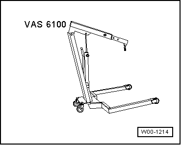
Drip tray for workshop hoist -VAS 6208-
Removing
l  
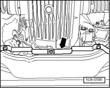
Lock carrier must be in service position → Chapter.
  Caution
To prevent damage to the electronic components when disconnecting the battery:
Observe notes on procedure for disconnecting the battery.
–  Disconnect earth cable at battery → Rep. Gr.27.
  WARNING
Hot steam/hot coolant can escape - risk of scalding.
t  The cooling system is under pressure when the engine is hot.
t  
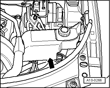
To allow pressure to dissipate, cover filler cap on expansion tank with cloth and open carefully.
–  Open filler cap on expansion tank.
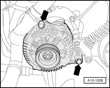
–  Remove poly V-belt for power steering pump, alternator and viscous fan → Chapter.
–  Pull out oil dipstick.
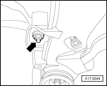
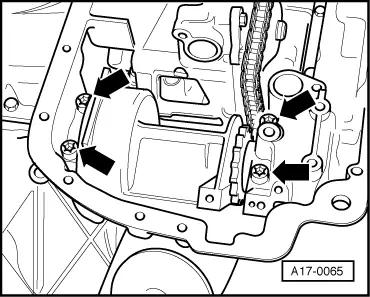
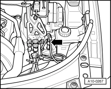
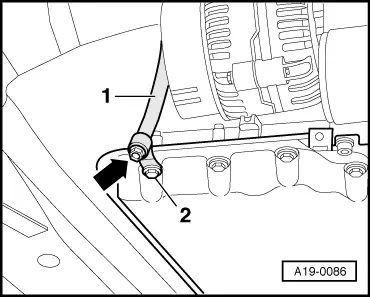
–  Unbolt dipstick guide tube on cylinder head (right-side).
  W00-10228
–  Remove cover -arrow- at power steering fluid reservoir.
  A10-0266
–  Unplug connector -arrow- for magnetic clutch for air conditioner compressor and move wiring clear.
  A10-0267
–  Detach the two refrigerant line brackets -1- and-3- from sump.
–  On vehicles with automatic gearbox, unbolt bracket for ATF lines (right-side) from sump -2-.
  A10-0337
  WARNING
Risk of injury caused by refrigerant.
The air conditioner refrigerant circuit must not be opened.
–  Unbolt air-conditioner compressor from bracket -arrows-.
  A10-0338
  Caution
Danger of damage to refrigerant lines and hoses.
Do NOT stretch, kink or bend refrigerant lines and hoses.
–  Tie up air conditioner compressor onto subframe, leaving refrigerant lines connected -arrow-.
  A10-0339
–  Unbolt bracket for A/C compressor -arrows-.
  A17-0107
–  Remove noise insulation (rear) -D--arrows C-.
  N02-0130
–  Unbolt bracket for noise insulation -arrow-.
  N34-0588
–  Remove bolts -arrows-.
–  Detach alternator to front.
–  Unbolt wiring from removed alternator.
  A10-1008
–  Detach wires -2- and -3- at starter; remove insulator from positive connection on starter.
–  Unscrew bolts -arrows- securing starter working from gearbox side and remove starter.
  A10-0341
–  If fitted, unplug electrical connector at oil level and oil temperature sender -G266--arrow-.
  A17-0158
–  Place drip tray for workshop hoist -VAS 6208- beneath engine.
–  Open drain plug -arrow- and drain off coolant.
–  Remove bolt -2- and detach coolant drain pipe -1- from cylinder block.
–  Drain off engine oil → Booklet802.
  A19-0086
–  Remove bolts and carefully detach sump (bottom section) -1- towards front.
  Note
Pay attention to chain guard in sump when detaching sump (bottom section).
  A17-0108
–  Mark position of nuts -1- and locating sleeves -2- on bottom of engine mountings (right and left).
  Note
Different mounting holes are provided for the different engine versions.
–  Unscrew nut -1- at bottom of engine mounting (right-side).
  A10-0088
–  Position support bracket -10 - 222 A- on wing mounting flanges (spindle faces to front).
  A37-0171
–  Remove eyelet of lifting tackle -2024 A-.
–  Re-insert pin -1- in centre hole of lifting tackle -2024 A- and secure with split pin.
–  Hang the pin of lifting tackle -2024 A- onto the spindle of support bracket -10 - 222 A-.
–  Engage lifting tackle -2024 A- in front and rear lifting eyes on engine.
  WARNING
Accident risk from loose components of lifting tackle.
The support hooks and retaining pins on the lifting tackle must be secured with locking pins -arrows-.
–  Take up weight of engine with the spindle of support bracket -10 - 222 A-, but do not lift.
  A17-0111
–  If fitted, unclip actuator rod for vehicle level sender at bottom transverse link -arrow-.
  A17-0147
–  Cut through cable ties -arrows-. Open retainer for starter wiring and take out wiring.
  A17-0045
–  Support subframe with workshop hoist.
  A17-0037
–  First remove front subframe bolts -2- and -3- (left and right). Then remove bolts -1-.
  Note
To avoid having to check and adjust wheel alignment, only loosen the front subframe mountings and lower the subframe at the front.
  A15-0220
–  On vehicles with manual gearbox, loosen nut -arrow- for gearbox mounting (left-side) until it is flush with lower end of bolt (turn approx. 4 threads).
  A17-0044
–  On vehicles with automatic gearbox, loosen rear bolt -2- for gearbox mounting (left-side) a few turns, then unscrew front bolt -1- for gearbox mounting (left-side).
  A17-0086
–  Loosen rear bolt -2- for gearbox mounting (right-side) several turns and remove front bolt -1- for gearbox mounting (right-side).
  A17-0043
–  Lower subframe slowly using workshop hoist -VAS 6100- or -V.A.G 1202 A-.
–  Remove workshop hoist.
–  If necessary, raise engine slightly using spindle of engine support bracket.
  Note
Do not lift engine to such an extent that pipes or coolant hoses are damaged or strained.
  A17-0037
–  Remove oil pump → Chapter.
–  Unscrew engine/gearbox connecting bolts in area of sump (top section).
–  Press dipstick guide tube out of sump (top section).
–  Unscrew bolts -1- and -2- for sump (top section).
–  Press sump (top section) off spring pins on cylinder block.
–  Push sump (top section) to left side of vehicle and take out.
  Note
  A17-0112
t  The balance shaft assembly can be unbolted from the sump (top section) -arrows-.
t  Remove torque reaction support before renewing sump (top section).
  A17-0065

Installing sump (top section) - engines with moulded gasket > < Removing and installing oil pump