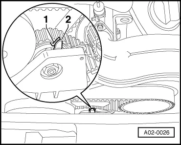
Caution | If a used belt runs in the opposite direction when it is refitted, this can cause breakage. |
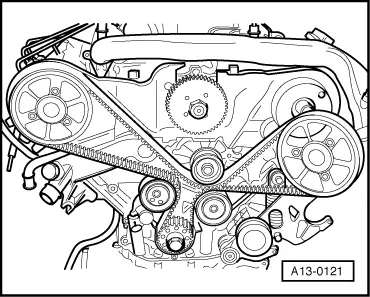
| Before removing, mark direction of rotation of toothed belt with chalk or felt-tipped pen for re-installation. |
|
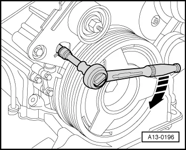
| –
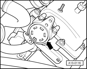
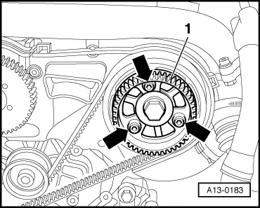
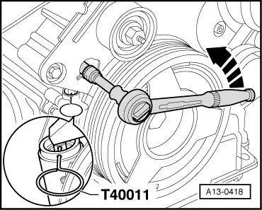
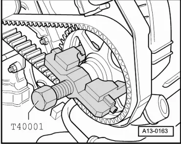
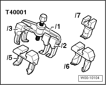
| Pull camshaft sprockets (left and right) off their tapers using two-arm puller -T40001- with claws -T40001/2-. |
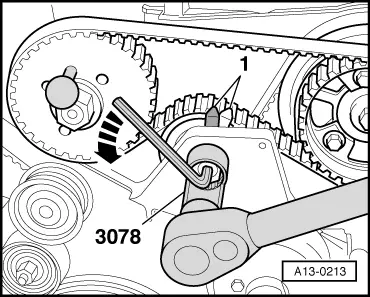
| –
| Unbolt camshaft sprocket, left-side (cylinder bank 2). |
| –
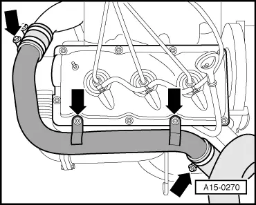
| Detach toothed belt from camshaft sprockets. |
| Installing (adjusting valve timing) |
| l
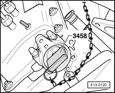
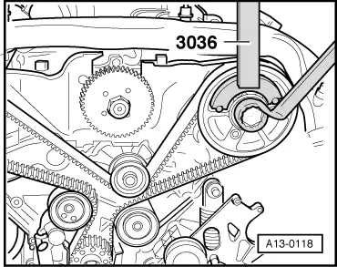
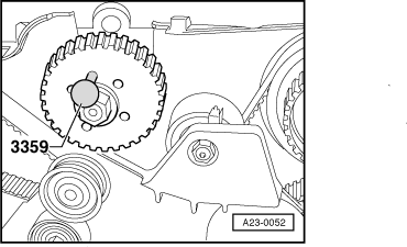
| Camshafts locked in position with camshaft holders -3458-. |
| l
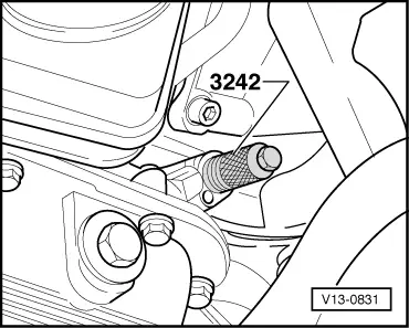
| Crankshaft locked in position with locking pin -3242-. |
| l
| Camshaft sprockets free to turn. |
| The valve timing must be adjusted as described below, even when the toothed belt has only been removed from the camshaft sprocket: |
| l
| The crankshaft must not be at “TDC” at any cylinder when the camshaft is turned. Otherwise, there is a risk of damage to valves and piston crowns. |
| l
| Do not use camshaft holders -3458- as counterhold tools. |
| l
| Adjustment can be performed with cold or warm engine. |
|
|
|


 Note
Note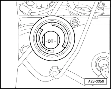
 WARNING