audi Workshop Repair Guides

Audi Workshop Service and Repair Manuals

Removing and installing exhaust manifold (right-side) with intermediate pipe > < Exhaust manifold with intermediate pipe - exploded view of components
Removing and installing exhaust manifold (left-side) with intermediate pipe
Removing
  Note
The exhaust manifold (left-side) can only be removed together with the intermediate pipe (left-side).
l  Lock carrier must be in service position → Chapter.
   
–  Detach caps on engine cover panel.
–  Unbolt and remove engine cover panel -arrows-.
–  Remove poly V-belt for air conditioner compressor → Chapter.
  A10-0202
–  Remove cover -arrow- at power steering fluid reservoir.
  A10-0266
–  Unplug connector -arrow- for magnetic clutch for air conditioner compressor and move wiring clear.
  A10-0267
–  Detach the two refrigerant line brackets -1- and-3- from sump.
  A10-0337
  WARNING
Risk of injury caused by refrigerant.
The air conditioner refrigerant circuit must not be opened.
–  Unbolt air-conditioner compressor from bracket -arrows-.
  A10-0338
  Caution
Danger of damage to refrigerant lines and hoses.
Do NOT stretch, kink or bend refrigerant lines and hoses.
–  Tie up air conditioner compressor onto subframe, leaving refrigerant lines connected -arrow-.
  A10-0339
–  Remove heat shield above turbocharger -arrows-.
  A34-0135
–  Unbolt front exhaust pipe from connection for turbocharger -arrows-.
  A10-0206
–  If installed, remove cross member -1-.
  Caution
Risk of damage to flexible joints in front exhaust pipe
Do not bend flexible joints in front exhaust pipe more than 10°.
–  Remove front exhaust pipe together with catalytic converter -arrows-.
  Note
Shown for vehicle with front-wheel drive in illustration.
  A34-0136
–  Unscrew nuts -arrows- for exhaust manifold (accessible from below).
  A26-0209
–  Unbolt coolant expansion tank -arrows 1-.
–  Detach wire for coolant shortage indicator switch -F66- and move coolant expansion tank to one side with coolant hoses -2- attached.
  A10-0278
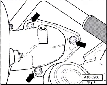
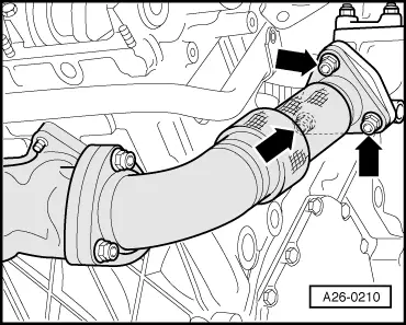
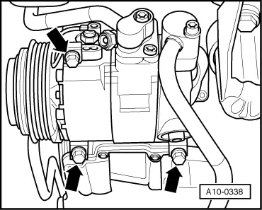
–  Unbolt exhaust pipe from turbocharger -arrows- (accessible from above).
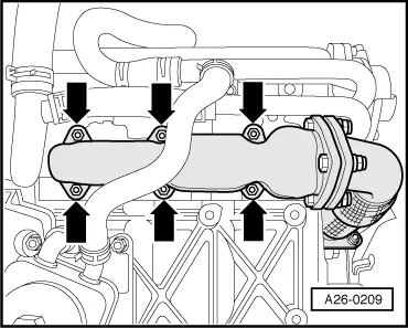
–  Take out exhaust manifold with intermediate pipe upwards.
–  Separate exhaust manifold and intermediate pipe if necessary.
Installing
Installation is carried out in the reverse order; note the following:
  Note
Renew gaskets and self-locking nuts.
–  Note installation position of gaskets for exhaust manifold:
l  Aluminium side should face towards cylinder head
–  Install front exhaust pipe with main catalytic converter: vehicles with front-wheel drive → Chapter, vehicles with four-wheel drive → Chapter.
–  Align exhaust system so it is free of stress: vehicles with front-wheel drive → Chapter, vehicles with four-wheel drive → Chapter.
–  Install poly V-belt for air conditioner compressor → Chapter.
Tightening torques
  A26-0210
ComponentNm
Exhaust manifold to cylinder head22
Intermediate pipe to:Exhaust manifold22
Intermediate flange22
Front exhaust pipe with catalytic converter to:Turbocharger25
Gearbox support25
Heat shield to turbocharger10
Air conditioner compressor to bracket22
Underbody cross member to body20


Removing and installing exhaust manifold (right-side) with intermediate pipe > < Exhaust manifold with intermediate pipe - exploded view of components