audi Workshop Repair Guides

Audi Workshop Service and Repair Manuals

Attaching engine to repair stand > < Engine data
6-Cylinder engine (5-valve turbo), Mechanics
Removing and installing engine

Notes:

  • ◆ All cable ties which are released or cut open when removing the engine must be replaced in the same position when installing the engine.
  • ◆ The engine is removed from the front without the gearbox.
  • ◆ Catch drained-off coolant in a clean container for re-use or disposal.
  • ◆ Renew all gaskets and seals.
  • ◆ Do not open the air conditioner refrigerant circuit.
 
A34-0163
  • ‒ Obtain radio code on vehicles with coded radio.
  • ‒ With ignition switched off, disconnect battery earth strap.
  • ‒ → Unscrew bolts -arrows- and remove engine cover panels -A...C-.
  • ‒ Remove cover above air cleaner.
  • ‒ Remove plenum chamber cover.
 
A10-0018
  • ‒ → Remove noise insulation -arrows-.
  • ‒ Remove retaining bracket for noise insulation on subframe.
  • ‒ Drain off coolant
  • ‒ Remove front bumper:

=> General body repairs; Repair group 63; Front bumper; Removing and installing front bumper

  • ‒ Remove lock carrier

=> General body repairs; Repair group 50; Removing and installing lock carrier

 
A10-0631
  • ‒ → Remove viscous fan (counter-hold with pin wrench 3212).

Note:

Viscous fan has left-hand thread: turn in direction indicated.

 
A15-0062
  • ‒ Mark direction of rotation of ribbed belt.
  • ‒ → To slacken ribbed belt, turn to the right using a 17 mm ring spanner until the two holes are aligned with each other -arrow- and hold in position with mandrel 3204.

Note:

Mark direction of rotation of ribbed belt. The belt can break if it runs in the opposite direction when refitted.

  • ‒ Take off ribbed belt.
 
A10-0293
  • ‒ → Disconnect water hoses -1- and -2-.
  • ‒ Remove coolant reservoir (arrows).
  • ‒ Unplug connector for coolant level monitor.
  • ‒ Remove cover panel from cylinder head cover (cylinder bank 4-6).
 
A10-0333
  • ‒ → Pull off hose -1- going to vacuum reservoir.
 
A24-0150
  • ‒ → Remove air duct -arrows-.

 
A10-0295
Warning

Fuel system is under pressure. Before opening the system, place a cloth around the connection. Then release pressure by carefully loosening the connection.
  • ‒ → Disconnect fuel supply line and fuel return line -1- and -2-, and move fuel lines clear.
  • ‒ Pull hose off ACF valve -3-.
 
A10-0296
  • ‒ → Unplug connector -1- from air mass meter.
  • ‒ Unplug connectors -2- from ignition output stages, and move wiring clear.
  • ‒ Remove air cleaner.

 
A10-0327
  • ‒ → Unplug connector -1- for lambda probe at bulkhead.
  • ‒ Unplug connector -2- for knock sensor.
  • ‒ Unplug connector -3-.
  • ‒ Move wiring harness clear.
 
A10-0297
  • ‒ → Remove pressure hoses -arrows- between charge air coolers and pressure pipes (right and left).

 
A10-0298
  • ‒ Unscrew and disconnect cable from positive battery terminal.
  • ‒ Disconnect positive terminal from battery.
  • ‒ → Move wiring harness clear together with cable duct for starter -arrows-.
 
A10-0326
  • ‒ → Fit clamp (special tool 3094) on hose from power steering reservoir to power steering pump.
  • ‒ Disconnect power steering hose -arrow-.

 
A10-0300
  • ‒ → Disconnect hydraulic pipe -arrow-.
  • ‒ Unplug connector from speedometer sender.
  • ‒ Unplug connector from reverse gear switch.
 
A10-0219
  • ‒ → Take off wiper arms -arrows-.
  • ‒ Pull clips -1- off water deflector.
  • ‒ Pull clips -3- off water deflector (left and right).
  • ‒ Take off water deflector.
  • ‒ Unbolt cover -2- from electronics box.
  • ‒ Open electronics box in plenum chamber.

 
A10-0287
  • ‒ Unclip retainer for engine control unit.
  • ‒ → Detach engine control unit, release catches on connectors -2- and -3- and unplug connectors.
  • ‒ Unplug connectors -1-.
 
A10-0299
  • ‒ → Pull off brake servo hose -1- at bulkhead.
  • ‒ Unscrew and detach earth connection -3-.
  • ‒ Unplug connectors -2- and -5- at bulkhead, and pull lower parts of connectors out of their brackets.
  • ‒ Pull connectors -4- out of bracket and move wiring clear.
  • ‒ Remove bracket for plug connectors.
  • ‒ Pull both heater hoses off engine. To do this, disengage retainers on connector flange.
 
A10-0325
  • ‒ → Remove pressure hoses -arrows- between turbocharger and charge air cooler (left and right sides).
 
A10-0294
  • ‒ → Move starter cable -1- clear. To do this, cut open cable tie and unclip retainer -arrows-.
  • ‒ Remove alternator cooling hose -2-.

 
A10-0321
  • ‒ → Unbolt earth cable -arrow- from engine support.
 
A10-0319
  • ‒ → Release hose clamp -arrow-.
  • ‒ Remove intake pipe -1-.
  • ‒ Remove water pipe -2-.

 
A10-0317
  • ‒ → Remove torque reaction support -1-.
  • ‒ Release hose clamps -arrows-.
  • ‒ Remove water pipe -2-.
 
A10-0322
  • ‒ Place drip tray V.A.G 1306 under engine.
  • ‒ Remove oil filter.
  • ‒ → Release hose clamps -arrows-.
  • ‒ Remove oil cooler -1-.

 
A10-0301
  • ‒ → Unscrew exhaust gas temperature sensor -1- from right-hand turbocharger using special tool 3035.
  • ‒ Detach heat shield -2- from left and right turbochargers.
  • ‒ Unscrew upper bolts -3- from front exhaust pipes at left and right turbochargers.
 
A34-0138
  • ‒ → Detach guard plates -arrows- above left and right drive shafts from gearbox.

 
A10-0329
  • ‒ → Release hose clamps -1- from left and right turbocharger guard plates.
  • ‒ Unbolt left and right exhaust pipes -2- from turbochargers.
 
A10-0320
  • ‒ → Detach air conditioner pipes from sump -arrows-.

 
A10-0324
  • ‒ → Disconnect gearbox oil pipes -1-.
  • ‒ Detach oil pipe at turbocharger -2-.
 
A10-0323
Important
The air conditioner refrigerant circuit must not be opened.
  • ‒ → Remove air conditioner compressor -1...3-.
  • ‒ Move compressor clear to the side and attach it to the body with wire, leaving the pipes connected.

Notes:

  • ◆ Note position of guide bushes when installing.
  • ◆ When installing, insert bolt -1- into compressor first.
 
A10-0088
  • ◆ To prevent damage to the condenser and refrigerant pipes/hoses. ensure that the pipes and hoses are not stretched, kinked or bent.
  • ‒ → Mark positions of securing points -1- and locating sleeves -2- under engine mountings on right and left sides.
  • ‒ Unscrew nuts -1- at engine mountings on left and right sides.

Note:

When installing, ensure that locating sleeves -2- engage in position.

 
A10-0330
  • ‒ Set up support bar 10-222A with 10-222A1 on bolted flanges of wing panels.
  • ‒ → Using support bar 10-222A with 10-222A1 and extension 10-222A3, lift engine upwards.
  • ‒ Unscrew engine/gearbox bolts from underneath.
  • ‒ Remove support bar.
  • ‒ Unscrew engine/gearbox bolts from above.

 
A10-0331
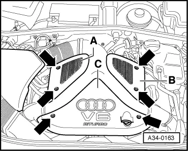
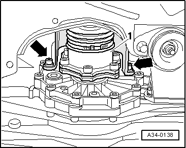
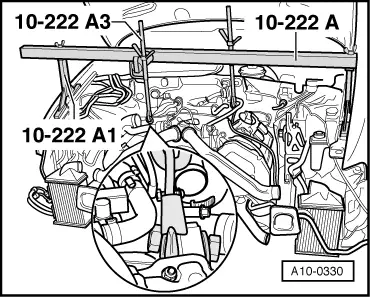
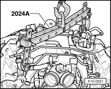
  • ‒ → Attach lifting tackle 2024 A at rear right and front left, and secure attachment points.

Note:

To balance the centre of gravity of the engine, secure the hook attachments in the positions shown in the illustration.


The hook attachments and locating pins on the lifting tackle must be secured with locking pins.
  • ‒ Remove front left wheel.
  • ‒ Support gearbox with trolley jack.
  • ‒ Bring workshop crane into position and hook up lifting tackle.

Note:

Check that all hoses, pipes and electrical wires between engine and gearbox have been disconnected.

  • ‒ Carefully pull out engine towards the front until there is sufficient clearance.
  • ‒ Guide engine forwards out of engine compartment.
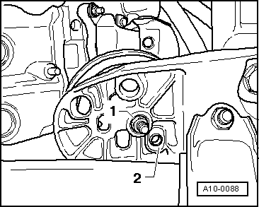
  • ‒ Remove spacer plate between engine and gearbox.

Attaching engine to repair stand > < Engine data