audi Workshop Repair Guides

Audi Workshop Service and Repair Manuals

Testing combination valve > < Testing secondary air inlet valve -N112
6-Cylinder engine (5-valve turbo), Mechanics
Secondary air system
Testing secondary air pump relay -J299 and activation
 
G24-0022

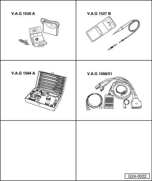
Special tools and workshop equipment required

  • ◆ V.A.G 1526 A
  • ◆ V.A.G 1527 B
  • ◆ V.A.G 1594 A
  • ◆ V.A.G 1598/31

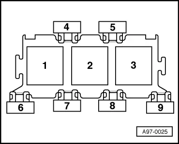
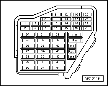
Fitting location=>Fitting locations overview

=> Motronic injection and ignition system; Repair group 24; Servicing Motronic injection system; Fitting locations overview

Test sequence

  • ‒ Start final control diagnosis and select secondary air pump relay -J299

=> Motronic injection and ignition system; Repair group 01; Final control diagnosis

 
A97-0025
    • ‒ → The secondary air pump relay should pick up and secondary air pump motor -V101 should run intermittently. (Relay is located in relay position 2 in 3-way relay carrier in electronics box on left side of plenum chamber).

A - If the relay does not pick up:

  • ‒ Test voltage supply of secondary air pump relay .
  • ‒ Test activation of secondary air pump relay => Page 26-69.

B - If the relay picks up but the secondary air pump motor does not run:

  • ‒ Test voltage supply of secondary air pump motor .

Testing voltage supply of secondary air pump relay

  • ‒ Switch off ignition.
  • ‒ Disconnect secondary air pump relay.
  • ‒ Connect multimeter (voltage measurement range) as follows:

3-way relay carrier (electronics box in plenum chamber) socket position 2:
contact

Test against

8

Engine earth

    • ‒ Specification: approx. battery voltage

If the specification is not obtained:

 
A97-0025
  • ‒ Carry out the following tests (marked with dots):
  • ● → Test fuse No. S130 (40 A) in 3-way relay carrier in electronics box, in plenum chamber, socket position 7
  • ● Test for open circuit in wiring from battery + (terminal 30) via fuse No. S130 to secondary air pump relay -J299 (located in socket position 2 of 3-way relay carrier in electronics box in plenum chamber.)

=> Current flow diagrams, Electrical fault finding and Fitting locations

  • ‒ Connect multimeter (voltage measurement range) as follows:

3-way relay carrier (electronics box in plenum chamber) socket position 2:
contact

Test against

4

Engine earth

  • ‒ Operate starter briefly.
    • ‒ Specification: approx. battery voltage

If the specification is not obtained:

  • ‒ Carry out the following tests (marked with dots):
 
A97-0119
  • ● → Test fuse No. S234 (in fuse box, socket 34).
  • ● Test for open circuit in wiring from fuel pump relay to secondary air pump relay -J299 (located in 3-way relay carrier in electronics box in plenum chamber) via fuse No. S234 (socket 34 in fuse box):

=> Current flow diagrams, Electrical fault finding and Fitting locations

Testing activation of secondary air pump relay

  • ‒ Switch off ignition.
  • ‒ Disconnect secondary air pump relay.
  • ‒ Connect voltage tester V.A.G 1527 B as follows:

3-way relay carrier (electronics box in plenum chamber) socket position 2:
contact

Test against

6

Battery positive

  • ‒ Start final control diagnosis and select secondary air pump relay -J299.

=> Motronic injection and ignition system; Repair group 01; Final control diagnosis

    • ‒ The LED should flash.

If the LED does not flash:

  • ‒ Switch off ignition.
  • ‒ Connect test box V.A.G 1598/31 to wiring harness for engine control unit.Do notconnect to the engine control unit itself.

=> Motronic ignition and injection system; Repair group 24; Servicing Motronic injection system; Testing fuel pump relay and activation

  • ‒ Test for open circuit and short to positive or earth in the following wiring connection:

3-way relay carrier (electronics box in plenum chamber) socket position 2:
contact

Test box V.A.G 1598/31
socket

6

46

  • ‒ Rectify any open/short circuit as necessary.

If no fault is found:

  • ‒ Fit a new secondary air pump relay -J299.

Testing voltage supply to secondary air pump motor

  • ‒ Unplug connector from secondary air pump motor -V101.
  • ‒ Connect voltage tester V.A.G 1527 B between contacts 1 and 2.
  • ‒ Start final control diagnosis and select secondary air pump relay -J299.

=> Motronic injection and ignition system; Repair group 01; Final control diagnosis

    • ‒ The LED should flash.

If the LED does not flash:

  • ‒ Carry out the following tests (marked with dots):
  • ● Test for open circuit in wiring from connector for secondary air pump motor -V101 to secondary air pump relay -J299 (located in 3-way relay carrier in electronics box in plenum chamber, socket position 2)

=> Current flow diagrams, Electrical fault finding and Fitting locations

  • ● Test for open circuit in wiring from connector on motor -V101 to earth connection 1 in engine compartment wiring harness:

=> Current flow diagrams, Electrical fault finding and Fitting locations

If no fault is found:

  • ‒ Renew secondary air pump motor -V101.

Testing combination valve > < Testing secondary air inlet valve -N112