
A4 Mk1
| Cylinder head - exploded view of components |
 Note
Note| The illustration shows the left cylinder head for “engine generation III” with oil pipes. |

| 1 - | Cylinder head gasket |
| q | Renewing → Chapter „Removing cylinder head (left-side)“ and → Chapter „Removing cylinder head (right-side)“ |
| q | Installation position: Part No. towards cylinder head |
| q | If renewed, refill system with fresh coolant |
| 2 - | Cylinder head |
| q | Removing: left-side → Chapter; right-side → Chapter. |
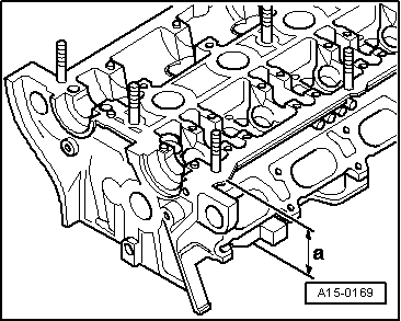
| q | Checking for distortion → Fig. |
| q | Machining limit → Fig. |
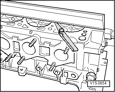
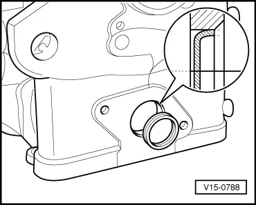
| q | Driving sealing cap into cylinder head → Fig. |
| q | Installing → Chapter |
| q | If renewed, refill system with fresh coolant |
| 3 - | Lifting eye |
| 4 - | 25 Nm |
| 5 - | Centering pin for intake manifold |
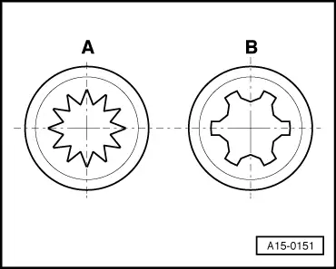
| 6 - | Cylinder head bolt |
| q | Renew |
| q | Different bolts → Fig. |
| q | Note correct sequence when loosening → Anchor and → Anchor |
| q | Note correct sequence when tightening → Anchor |
| 7 - | Intake manifold gasket |
| q | Renew |
| 8 - | Intake manifold |
| q | Removing and installing → Chapter |
| 9 - | 10 Nm |
| q | Tighten in stages and in diagonal sequence |
| 10 - | Filler cap |
| 11 - | Seal |
| q | Renew if damaged or leaking |
| 12 - | Rubber grommet |
| 13 - | Cover panel for cylinder head cover |
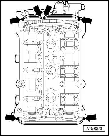
| 14 - | 10 Nm |
| q | Note correct sequence when tightening → Anchor or → Anchor |
| 15 - | Cylinder head cover |
| q | Removing and installing: left-side → Chapter, right-side → Chapter |
| 16 - | Gaskets for cylinder head cover |
| q | Renew if damaged or leaking |
| q | Apply sealant at sealing points before installing → Fig.; Sealant → Parts catalogue |
| 17 - | Combination valve for secondary air system |
| 18 - | 10 Nm |
| 19 - | Gasket |
| q | Renew |
| 20 - | 10 Nm |
| 21 - | Coolant pipe (rear) |
| 22 - | O-ring |
| q | Renew |
| 23 - | Sealing cap |
| q | Removing and installing → Chapter |
|
|
|
|
|
|
|
|