audi Workshop Repair Guides

Audi Workshop Service and Repair Manuals

Installing sump (top section) - "engine generation II” > < Installing sump (bottom section) - engines with liquid gasket
Removing sump (top section)
   
Removing sump (top section)
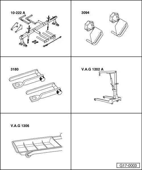
Special tools and workshop equipment required
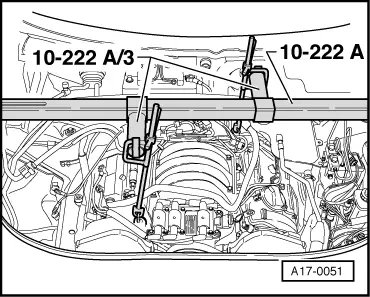
t  Support bracket -10-222 A- and adapter -10-222 A/4-
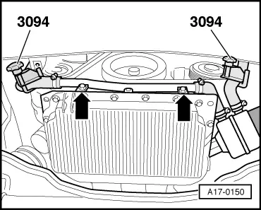
t  Hose clamps for hoses up to 25 mm Ø -3094-
t  Retainer -3180-
t  Workshop hoist -VAS 6100- or -V.A.G 1202 A-
t  Drip tray for workshop hoist -VAS 6208- or -V.A.G 1306-

   
t  Used oil collection and extraction unit -V.A.G 1782-
  W00-10211
t  Locking pin -3204-
t  TORX wrench T45
  W00-0461
Procedure
  Caution
Observe notes on procedure for disconnecting the battery → Rep. Gr.27.
–  Detach rubber seal from plenum chamber cover in direction of -arrow-.
–  Detach plenum chamber cover -1- towards the front.
  A20-0564
–  With ignition switched off, disconnect battery earth cable -arrow-.
  N27-0090
–  Remove engine cover panel -arrows-.
  A10-0113
–  Detach cover -2- from air cleaner.
–  Unbolt air duct -1- for air cleaner at lock carrier and lift out.
  A10-0263
–  On vehicles with secondary air system, turn connecting pipe through 45° to the right -arrow- and detach from air cleaner housing.
  A26-0149
–  Remove air intake hose between air mass meter -G70- and air intake elbow.
–  Unplug electrical connector at solenoid valve 1 for activated charcoal filter system -N80- and detach solenoid valve from bracket.
–  Detach electrical connector at air mass meter -G70-.
–  Unscrew and remove air cleaner housing.
  A10-0086
–  On vehicles with secondary air system, disconnect hose -arrow- from secondary air connecting pipe.
  A10-0474
Tensioning roller with hexagon flats:
  Note
Before removing, mark direction of rotation of poly V-belt with chalk or felt-tipped pen. If the belt runs in the opposite direction when it is refitted, this can cause breakage.
–  Turn the tensioner in the direction of the -arrow- using a 17 mm ring spanner to slacken the poly V-belt.
–  Lock tensioner in position by inserting locking pin -3204- in locating holes -arrows-.
–  Guide poly V-belt over viscous fan and detach belt.
  A15-0062
Tensioning roller with hexagon socket:
  Note
Before removing, mark direction of rotation of poly V-belt with chalk or felt-tipped pen. If the belt runs in the opposite direction when it is refitted, this can cause breakage.
–  Turn the tensioner in the direction of the -arrow- using a 10 mm hexagon key to slacken the poly V-belt.
–  Lock tensioner in position by inserting locking pin -3204- in locating holes -arrow 1- and -arrow 2-.
–  Guide poly V-belt over viscous fan and detach belt.
  A13-0215
Vehicles with throttle cable and cruise control system:
–  Detach vacuum hose -2- at vacuum unit for cruise control.
–  Unscrew bolts -1- and move vacuum unit downwards.
  A10-0470
All models:
–  Set up support bracket -10-222 A- with adapter -10-222 A/3- on wing panel flanges.
–  Connect support bracket to front and rear lifting eyes on engine.
–  Raise engine as far as possible with spindles of support bracket.
  A17-0051
–  Unbolt dipstick guide tube on cylinder head -arrow- and lift out upwards.
  A15-0312
–  Remove noise insulation -arrows-.
–  Place used oil collection and extraction unit -V.A.G 1782- under engine.
–  Drain off engine oil.
–  Remove front bumper → Rep. Gr.63.
–  Move lock carrier to service position → Rep. Gr.50.
  WARNING
Hot steam or hot coolant can escape when expansion tank is opened; cover filler cap with cloth and open carefully.
  A10-0018
–  Open filler cap on coolant expansion tank.
–  Place drip tray for workshop hoist -VAS 6208- under engine.
–  Turn drain plug -arrow- on radiator anti-clockwise, if necessary fit drain hose to connection.
  A10-0189
–  Also open coolant drain plug on engine -arrow-.
–  Drain off coolant.
  V10-1170
Vehicles with automatic gearbox:
–  Remove bracket for ATF pipes -arrows-.
  A37-0286
All models:
–  If fitted, unplug electrical connector -arrow- at oil level/temperature sender -G266- and move wiring clear.
  A17-0158
–  If fitted, unclip actuator rod for vehicle level sender at bottom transverse link -arrow-.
  A17-0147
–  Cut through cable ties -arrows-. Open retainer for starter wiring and take out wiring.
–  Unbolt torque reaction support and stop for torque reaction support.
  A17-0045
–  Clamp off both coolant hoses leading to oil cooler with hose clamps -3094-.
–  Place drip tray for workshop hoist -VAS 6208- under engine.
–  Unscrew coolant pipe -arrows- and detach it from hoses.
–  Unplug connector at oil pressure switch -F1- and move wiring clear.
  A17-0150
–  Mark positions of bolt connections -1- and locating sleeves -2- on bottom of engine mounts (left and right).
  Note
Different mounting holes are provided for the different engine versions.
–  Remove bottom nut -1- at engine mounting (left and right).
–  Remove engine mounting (left-side).
  A10-0088
–  First remove front subframe bolts -2- and -3- (left and right). Then unscrew bolts -1-.
  Note
To avoid having to check and adjust wheel alignment, only loosen the front subframe mountings and lower the subframe at the front.
–  Pivot anti-roll bar downwards.
  A15-0220
–  Detach wires -1- and -2- at starter and detach insulator at positive connection of starter.
–  Remove starter bolts -arrows- from gearbox side.
–  Unscrew clamp on right of top section of sump and move electrical wiring clear.
–  Remove starter.
  A10-0440
–  Remove sump (bottom section) -1-.
  A17-0108
Vehicles with “engine generation II”:
–  Unscrew cover plate -1-.
–  Remove gasket -2-.
  A17-0152
Vehicles with “engine generation III”:
–  Place used oil collection and extraction unit -V.A.G 1782- under engine.
–  Unbolt brackets -arrows- and pull off long oil supply pipe from below.
  A17-0071
–  Unscrew chain sprocket using TORX wrench T45 -arrow- and pull it off oil pump.
  A17-0072
–  Remove oil pump together with short oil supply pipe -arrows-.
  A17-0075
All models:
–  Unscrew engine/gearbox securing bolts in area of sump (top section).
–  Unscrew bolts -1- for sump (top section).
–  Press sump (top section) off spring pins on cylinder block.
–  Remove sump (top section).
  A17-0151

Installing sump (top section) - "engine generation II” > < Installing sump (bottom section) - engines with liquid gasket