
A4 Mk1
| Crankshaft - exploded view of components |
 Note
Note| t | The illustration shows the “engine generation III” version as an example for both engine generations. |
| t | Secure engine to engine and gearbox support -VAS 6095- prior to performing assembly work → Chapter. |
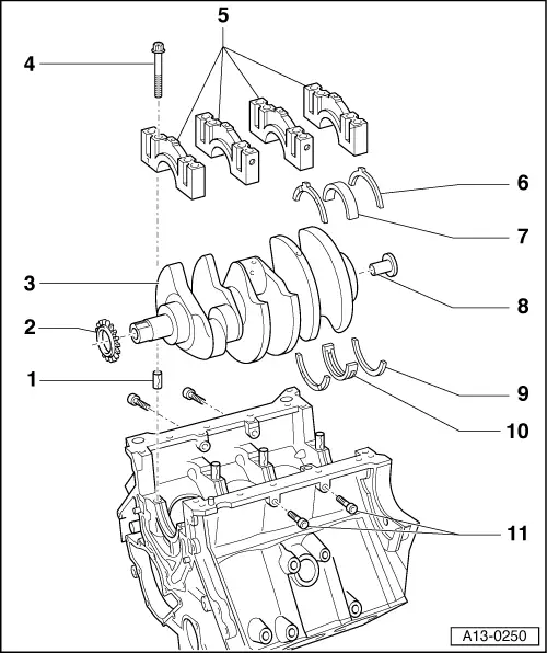
| 1 - | Dowel sleeve |
| q | Insert in cylinder block |
| 2 - | Chain sprocket |
| q | “Engine generation III” only |
| q | Removing and installing → Chapter |
| 3 - | Crankshaft |
| q | Measuring axial clearance → Chapter |
| q | Measuring radial clearance → Chapter |
| q | Do not rotate the crankshaft when checking the radial clearance |
| q | Crankshaft dimensions → Chapter |
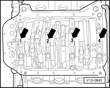
| 4 - | Bearing cap bolts |
| q | Renew |
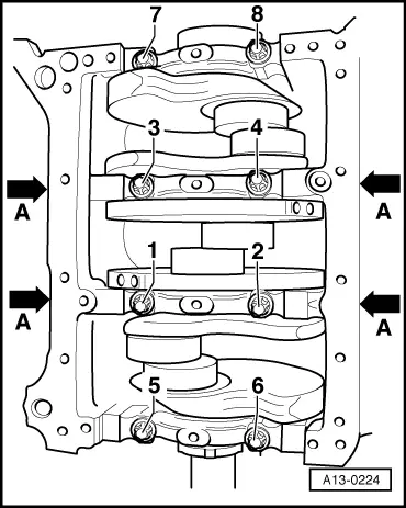
| q | Tightening sequence → Fig. |
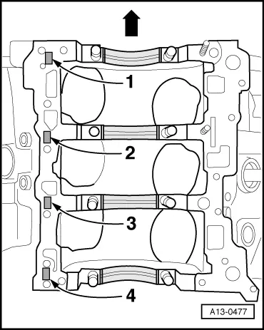
| 5 - | Bearing cap |
| q | Note marking → Fig. |
| q | Installing → Fig. |
| 6 - | Thrust washer |
| q | Only fitted on 4th crankshaft bearing |
| q | Oil grooves face outwards |
| q | Note location |
| q | Measuring axial clearance of crankshaft → Chapter |
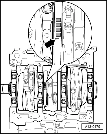
| 7 - | Bearing shell for bearing cap |
| q | Without oil groove |
| q | Do not interchange used bearing shells (mark positions) |
| q | Install new bearing shells for the bearing caps with the correct coloured markings → Fig. |
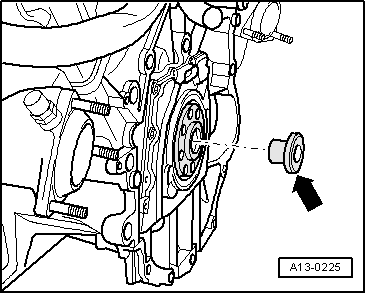
| 8 - | Bearing bush |
| q | Automatic gearbox only |
| q | Driving in → Fig. |
| 9 - | Thrust washer |
| q | Only fitted on 4th crankshaft bearing |
| q | Oil grooves face outwards |
| q | Measuring axial clearance of crankshaft → Chapter |
| 10 - | Bearing shell for cylinder block |
| q | With oil groove |
| q | Do not interchange used bearing shells (mark positions) |
| q | Install new bearing shells for the cylinder block with the correct coloured markings → Fig. |
| 11 - | Bearing cap bolts |
| q | Tightening sequence → Fig. |
|
|
| Letter on cylinder block | Colour coding of bearing | |
| G | = | Yellow |
| B | = | Blue |
| S | = | Black |
|
|
| Letter on crankshaft | Colour coding of bearing | |
| G | = | Yellow |
| B | = | Blue |
| S | = | Black |
|
|
Note
|
|