
A4 Mk1
| Exhaust system on vehicles with front-wheel drive - exploded view of components |
 Note
Note| The illustration shows the exhaust system on vehicles with exhaust emissions standard “EU4”. |

| 1 - | 25 Nm |
| 2 - | Mounting |
| q | Renew if damaged |
| 3 - | 27 Nm |
| q | Renew |
| 4 - | Exhaust manifold |
| q | For cylinder bank 1 (right-side) |
| 5 - | Gasket |
| q | Renew |
| 6 - | Front exhaust pipe with starter catalytic converter and main catalytic converter |
| q | For cylinder bank 1 (right-side) |
| q | With flexible joint |
| q | Do not bend flexible joint more than 10° - otherwise it can be damaged |
| q | Protect against knocks and impact |
| q | Align exhaust system so it is free of stress → Chapter |
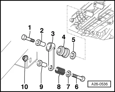
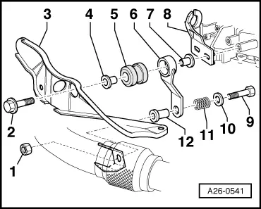
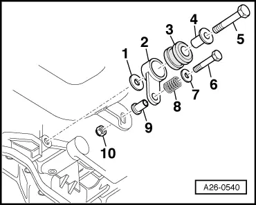
| q | Components of exhaust pipe mountings for vehicles with manual gearbox → Fig. |
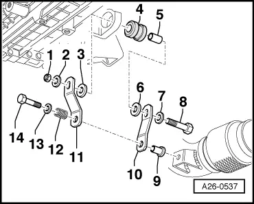
| q | Components of exhaust pipe mountings for vehicles with automatic gearbox → Fig. |
| 7 - | Lambda probe (before catalytic converter), 55 Nm |
| q | For cylinder bank 1 (right-side) |
| q | Threads of new Lambda probes are already greased with assembly paste; the paste must not get into the slots on the probe body |
| q | When re-using the old Lambda probe, grease thread with high-temperature lubricant; the paste must not get into the slots of the probe body. High-temperature paste → Parts catalogue |
| 8 - | Lambda probe (after catalytic converter), 55 Nm |
| q | For cylinder bank 1 (right-side) |
| q | Threads of new Lambda probes are already greased with assembly paste; the paste must not get into the slots on the probe body |
| q | When re-using the old Lambda probe, grease thread with high-temperature lubricant; the paste must not get into the slots of the probe body. High-temperature paste → Parts catalogue |
| 9 - | Exhaust manifold |
| q | For cylinder bank 2 (left-side) |
| 10 - | Gasket |
| q | Renew |
| 11 - | 27 Nm |
| q | Renew |
| 12 - | Lambda probe (before catalytic converter), 55 Nm |
| q | For cylinder bank 2 (left-side) |
| q | Threads of new Lambda probes are already greased with assembly paste; the paste must not get into the slots on the probe body |
| q | When re-using the old Lambda probe, grease thread with high-temperature lubricant; the paste must not get into the slots of the probe body. High-temperature paste → Parts catalogue |
| 13 - | Lambda probe (after catalytic converter), 55 Nm |
| q | For cylinder bank 1 (left-side) |
| q | Threads of new Lambda probes are already greased with assembly paste; the paste must not get into the slots on the probe body |
| q | When re-using the old Lambda probe, grease thread with high-temperature lubricant; the paste must not get into the slots of the probe body. High-temperature paste → Parts catalogue |
| 14 - | Front exhaust pipe with starter catalytic converter and main catalytic converter |
| q | For cylinder bank 2 (left-side) |
| q | With flexible joint and front silencer |
| q | Do not bend flexible joint more than 10° - otherwise it can be damaged |
| q | Protect against knocks and impact |
| q | Align exhaust system so it is free of stress → Chapter |
| q | Components of exhaust pipe mountings for vehicles with manual gearbox → Fig. |
| q | Components of exhaust pipe mountings for vehicles with automatic gearbox → Fig. |
| 15 - | Clamp (front) |
| q | Align exhaust system so it is free of stress before tightening clamp → Chapter |
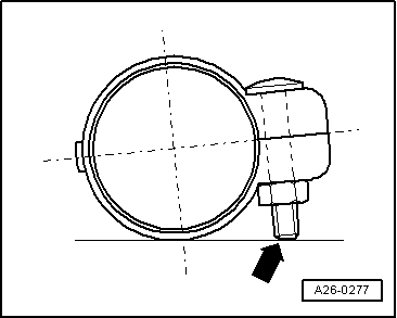
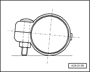
| q | Installation position → Fig. |
| q | Tighten bolt connections evenly. |
| 16 - | 40 Nm |
| 17 - | Clamp (front) |
| q | Align exhaust system so it is free of stress before tightening clamp → Chapter |
| q | Installation position → Fig. |
| q | Tighten bolt connections evenly. |
| 18 - | 40 Nm |
| 19 - | Mounting |
| q | Renew if damaged |
| 20 - | 25 Nm |
| 21 - | Rear silencer |
| q | Combined in one unit with centre silencer as original equipment. Can be renewed individually for repair purposes |
| q | Cutting point → Anchor |
| q | Align exhaust system so it is free of stress → Chapter |
| 22 - | Clamp (rear) |
| q | For separate replacement of centre and rear silencers |
| q | Align exhaust system so it is free of stress before tightening clamp → Chapter |
| q | Installation position → Fig. |
| q | Tighten bolt connections evenly. |
| 23 - | 40 Nm |
| 24 - | Mounting |
| q | Renew if damaged |
| 25 - | 25 Nm |
| 26 - | Centre silencer |
| q | With front silencer |
| q | Combined in one unit with rear silencer as original equipment. Can be renewed individually for repair purposes |
| q | Cutting point → Anchor |
| q | Align exhaust system so it is free of stress → Chapter |
|
|
|
|
|
|
|
|
|
|