audi Workshop Repair Guides

Audi Workshop Service and Repair Manuals

Checking combination valve for secondary air system for proper operation and leakage > < Checking secondary air inlet valve N112
Checking secondary air pump relayJ299 or J316 and activation
   
Checking secondary air pump relay -J299- or -J316- and activation
Special tools and workshop equipment required
t  Hand-held multimeter -V.A.G 1526 A- or -V.A.G 1526 B-
t  Voltage tester -V.A.G 1527 B-
t  Auxiliary measuring set -V.A.G 1594 A- or -V.A.G 1594 C-
t  Test box -V.A.G 1598/22- (vehicles with throttle cable)
t  Test box -V.A.G 1598/31- (vehicles with electronic throttle)
t  Vehicle diagnostic, testing and information system -VAS 5051- with diagnosis lead -VAS 5051/1-

Test conditions
l  Vehicle diagnostic, testing and information system -VAS 5051- with diagnosis lead -VAS 5051/1- is connected; vehicle self-diagnosis and vehicle system “01 - Engine electronics” is selected. When doing this, the ignition must be switched on.
l  Fault memory of engine control unit interrogated.
   
Test sequence
Display on -VAS 5051-
–  From the menu -1- select the diagnostic function “03 - Final control diagnosis”.
–  Press the button until the secondary air pump relay -J299- or -J316- is activated.
  A01-0122
l  The secondary air pump relay -J299- or -J316--item 2- (located in electronics box in plenum chamber) should pick up and the secondary air pump motor -V101- should start up intermittently.
–  Exit function “03 - Final control diagnosis” by pressing the key, and switch off the ignition.
A - If the relay does not pick up:
–  Check voltage supply of secondary air pump relay -J299- or -J316- → Anchor.
–  Check activation of secondary air pump relay -J299- or -J316- → Anchor.
B - If the relay picks up but the secondary air pump motor -V101- does not run:
–  Check voltage supply of secondary air pump motor -V101- → Anchor.
  A26-0357
Checking voltage supply of secondary air pump relay -J299- or -J316-
–  Run windscreen wipers to the vertical position.
–  Detach rubber seal from plenum chamber cover in direction of -arrow-.
–  Detach plenum chamber cover -1- towards the front.
  A20-0564
–  Remove cover for electronics box in plenum chamber -arrows-.
  A10-0761
–  Disconnect secondary air pump relay -J299- or -J316--item 2-.
  A26-0357
–  Connect up multimeter (voltage measuring range) between relay socket, contact -8- and earth.
l  Specification: approx. battery voltage
  A24-0298
If specification is not obtained:
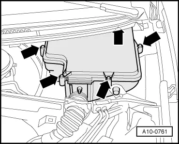
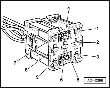
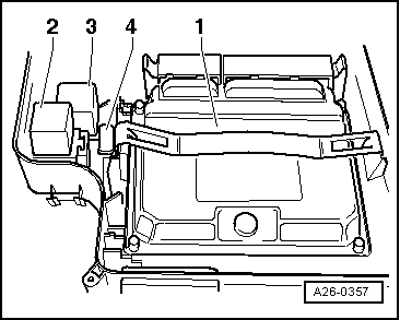
–  Check secondary air pump fuse -S130- in position -4- on relay and fuse holder in electronics box (plenum chamber).
–  Use current flow diagram to check for open circuit in wiring from battery + (terminal 30), via secondary air pump fuse -S130- in position -4-, to secondary air pump relay -J299- or -J316--item 2- in electronics box (plenum chamber).
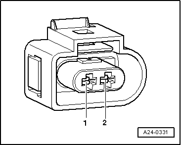
–  Connect multimeter (voltage measuring range) between relay socket, contact 4 and earth.
–  Operate the starter briefly.
l  Specification: approx. battery voltage
If specification is not obtained:
–  Repair wiring harness according to current flow diagram.
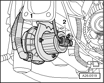
Checking activation of secondary air pump relay -J299- or -J316-
–  Switch off ignition.
–  Disconnect secondary air pump relay -J299- or -J316-.
  A26-0357
–  Connect up voltage tester -V.A.G 1527 B- between relay socket contact -6- and battery positive.
–  Repeat function “03 - Final control diagnosis”.
–  Press the button until the secondary air pump relay -J299- or -J316- is activated.
l  The LED should flash.
–  Exit function “03 - Final control diagnosis” by pressing the key, and switch off the ignition.
If the LED does not flash:
–  Connect test box -V.A.G 1598/22- or -V.A.G 1598/31- to wiring harness leading to engine control unit, but do not connect engine control unit itself → Rep. Gr.24.
–  Check for open circuit and short to positive or earth in the following wiring:
Vehicles with throttle cable:
  A24-0298
Relay socket
contact
Test box -V.A.G 1598/22-
Socket
-6-30

Vehicles with electronic throttle:
   
Relay socket
contact
Test box -V.A.G 1598/31-
Socket
-6-46

All models:
–  Repair wiring connection if necessary.
If no fault in wire is detected:
–  Renew secondary air pump relay -J299- or -J316-.
   
Checking voltage supply for secondary air pump motor -V101-
–  Remove noise insulation -arrows-.
  A10-0018
–  Unplug electrical connector -2- at secondary air pump motor -V101--item 1-.
  A26-0519
–  Connect voltage tester -V.A.G 1527 B- between contacts -1- and -2-.
–  Repeat function “03 - Final control diagnosis”.
–  Press the button until the secondary air pump relay -J299- or -J316- is activated.
l  The LED should flash.
–  Exit function “03 - Final control diagnosis” by pressing the key, and switch off the ignition.
  A24-0331
If the LED does not flash:
–  Use current flow diagram to check for open circuit in wiring between connector at secondary air pump motor -V101- and secondary air pump relay -J299- or -J316-, -item 2- (in electronics box in plenum chamber).
–  Use current flow diagram to check for open circuit in wiring between connector at secondary air pump motor -V101- and earth.
If no fault is found:
–  Renew secondary air pump.
  A26-0357

Checking combination valve for secondary air system for proper operation and leakage > < Checking secondary air inlet valve N112