
A4 Mk1
|
 Note
Note
|
|
|
|
|
|
 WARNING
|
|
Note
|
|
|
|
|
|
|
|
|
|
Note
|
|
|
|
|
|
| Component | Nm | |
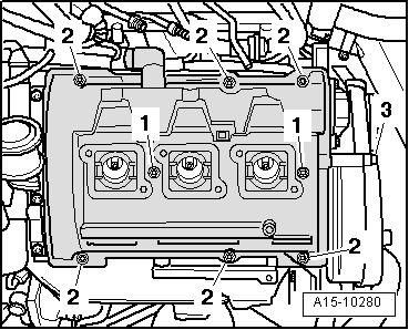
| Cylinder head cover to cylinder head | 10 | |
| Toothed belt cover to cylinder head cover | 10 | |
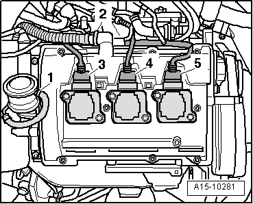
| Ignition coils to cylinder head cover | 10 | |
| Bracket to: | Toothed belt cover | 10 |
| Bracket | 10 | |
| Air pipe to cylinder head cover | 10 | |
| Fuel supply line to fuel rail | 22 | |
| Air duct to intake manifold | 10 | |
| Hose clips (9 mm wide) | 3 | |
| Hose clips (13 mm wide) | 5.5 | |