audi Workshop Repair Guides

Audi Workshop Service and Repair Manuals

Secondary air pump - exploded view of components > < Checking secondary air pump relay J299 and activation
Checking combination valves for secondary air system for correct operation and leakage
Special tools and workshop equipment required
   
t  Hand-operated vacuum pump with accessories -V.A.G 1390-
  W00-0515
Procedure
–  Unfasten screw connections -arrows- and detach engine cover panels -A ... C-.
  A34-0163
–  Unscrew hose connections and bolt connections on the air duct at the points indicated by -arrows- and remove the air duct.
  A24-0150
Combination valve for secondary air (left-side):
–  Unbolt coolant expansion tank -2--arrows-.
–  Unplug electrical wire for coolant shortage indicator switch -F66- at bottom of expansion tank and move expansion tank to one side with coolant hoses -1- and -3- attached.
  A10-0259
Combination valve for secondary air (right-side):
–  Remove cover -1- at right of engine compartment.
  Note
Disregard items marked -2- and -3-.
  A10-0863
Continued for both combination valves for secondary air system:
–  Detach air intake hose -3- and vacuum hose -2- from relevant combination valve for secondary air system.
  Note
Disregard -item 1-.
  A26-10266
–  Connect suitable hose -arrow- to air intake hose connection on combination valve for secondary air.
  A26-10246
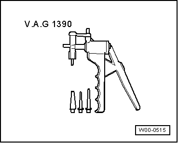
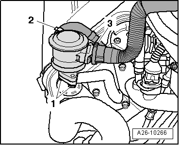
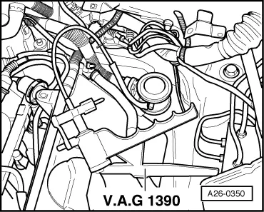
–  Connect the hand-operated vacuum pump -V.A.G 1390- to vacuum connection of combination valve for secondary air.
–  Blow gently into hose (do not use compressed air).
l  The combination valve for secondary air system should be closed; it should not be possible to blow through the hose.
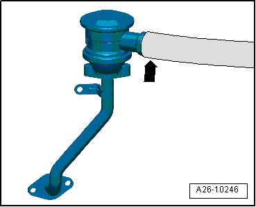
–  Use hand-operated vacuum pump to generate vacuum.
l  The combination valve for secondary air system should open; it should now be possible to blow through the hose.
If combination valve for secondary air system does not react as described:
–  Renew combination valve for secondary air system: on left-side → Chapter, on right-side → Chapter.
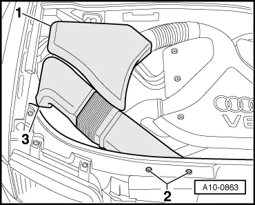
Installation is carried out in the reverse order; note the following:
  Note
Secure all hose connections with the correct type of hose clips (same as original equipment) → Parts catalogue.
Tightening torque
  A26-0350
ComponentNm
Air duct to intake manifold10


Secondary air pump - exploded view of components > < Checking secondary air pump relay J299 and activation