
A4 Mk1
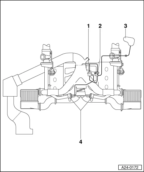
| Connection diagram for charge pressure control and overrun air recirculation control |
| Charge pressure control |
 Note
Note| The turbochargers of the 6-cylinder biturbo engine are pressure controlled. The charge pressure control solenoid valve -N75- controls both turbochargers together. |

| 1 - | Turbocharger |
| q | Bank 1 (right-side) |
| 2 - | Solenoid valve for charge pressure control -N75- |
| 3 - | Connecting piece |
| q | For crankcase breather |
| 4 - | Turbocharger |
| q | Bank 2 (left-side) |
| Overrun air recirculation control |
| 1 - | Turbocharger air recirculation valve -N249- |
| q | Checking → Chapter |
| 2 - | Non-return valve |
| q | Installation position: arrow points direction of flow |
| 3 - | Vacuum reservoir |
| 4 - | Mechanical air recirculation valves |
| q | Checking → Chapter |