audi Workshop Repair Guides

Audi Workshop Service and Repair Manuals

Checking fuel gauge sender -G - vehicles with 6-cylinder engine > < Testing sender for low fuel level -G210 - vehicles with 6-cylinder engine
Fuel supply system - Diesel engines
Fuel supply system - front-wheel drive
Removing and installing fuel delivery unit - vehicles with 6-cylinder engine
 
G20-0014

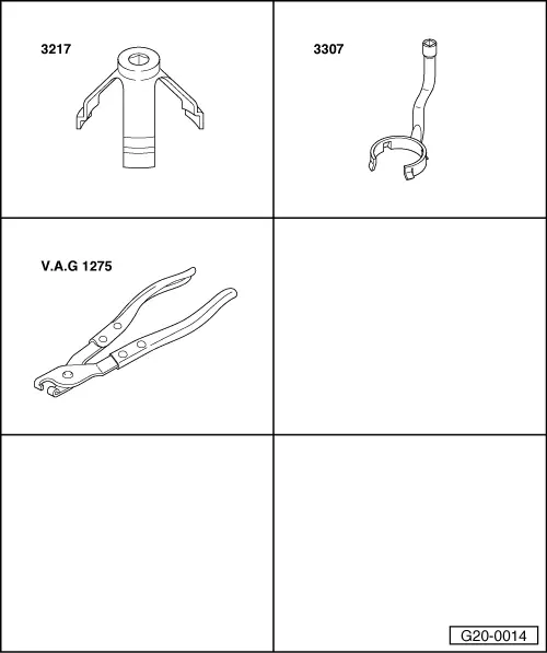
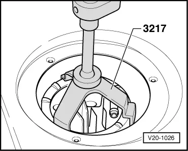
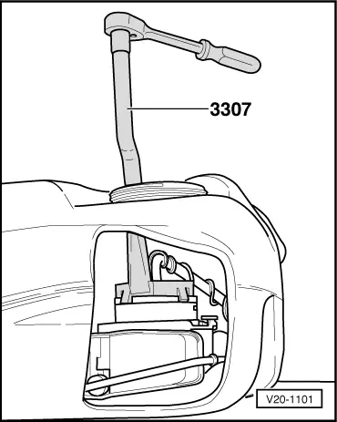
Special tools and workshop equipment required

  • ◆ Ring nut spanner 3217
  • ◆ Fuel pump spanner 3307
  • ◆ Hose clamp pliers V.A.G 1275
 
A20-0319

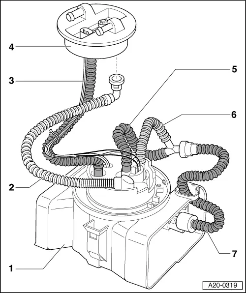
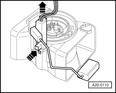
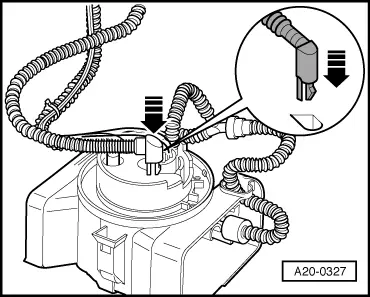
Note:

The illustration shows the correct routing of hoses inside the tank.

  • Baffle housing
  • Fuel return hose
  • Fuel supply hose
  • Flange
  • Hose
    • ◆ From fuel pump to Y-connector
  • Fuel hose
    • ◆ From fuel delivery unit to Y-connector
  • Fuel hose
    • ◆ From Y-connector to suction jet pump

Observe safety precautions.

Observe rules for cleanliness => Page 20-3.

Removing

 
A20-0305
  • ‒ The fuel tank must not be more than 3/4 full when removing the fuel delivery unit. Drain fuel tank if necessary.
    Procedure => Page 20-12.
  • ‒ Detach floor trim in luggage compartment.
  • ‒ Unbolt cover for flange.
  • ‒ → Release and unplug connectors -1- and -2-.

 
A20-0333
  • ‒ → Disconnect fuel return pipe -1- and fuel supply pipe -2- from flange.
 
V20-1026
  • ‒ → Remove union nut with spanner 3217.
  • ‒ Remove flange and seal out of opening in fuel tank.
  • ‒ Unplug connector for fuel gauge sender on inside of flange.

 
A20-0307
  • ‒ → Disconnect elbow connector on fuel return hose from inner section of baffle housing by pulling upwards -arrow-.
 
A20-0110
  • ‒ → Press retaining tab and at the same time pull sender unit out of baffle housing in fuel tank -arrows-.

 
A20-0308
  • ‒ → Press release catches -arrows- and disconnect fuel hose at Y-connector.
  • ‒ Place hose going to suction jet pump in fuel tank.
 
V20-1101
  • ‒ → Insert fuel pump spanner 3307 through opening in fuel tank and apply spanner to fuel delivery unit.
  • ‒ Using spanner 3307, turn fuel delivery unit anti-clockwise as far as it will go (approx. 15°), and take out fuel delivery unit.

Installing

Install in reverse sequence; note the following points:

Note:

Secure all hose connections with the correct hose clips (same as original parts)

=> Parts catalogue

  • ‒ Insert fuel delivery unit in fuel tank.
 
A20-0112
  • ‒ → Fit fuel delivery unit into outer section of baffle housing (in tank) so that notch -1- on fuel delivery unit is aligned with marking -2- on outer section of housing.
    • ‒ The fuel delivery unit should move down noticeably.
  • ‒ Apply fuel pump spanner 3307 and turn fuel delivery unit clockwise as far as it will go (approx. 15°). Notch -1- will then be aligned with marking -3- (bayonet fitting).

 
A20-0308
  • ‒ → Connect fuel pipe to Y-connector so that catches engage -arrows-.
  • ‒ Insert Y-connector with fuel pipes in fuel tank and position to one side.

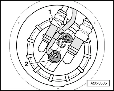
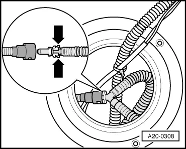
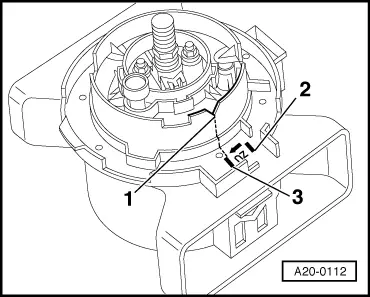
Note:

Ensure that fuel hose going from baffle housing to Y-connector is engaged in retainer in outer section of baffle housing.

  • ‒ Insert fuel gauge sender into guide on outer section of baffle housing and press down until it clicks into place.
 
A20-0327
  • ‒ → Plug elbow connector of fuel return hose onto inner section of baffle housing so that it engages -arrow-.
  • ‒ Wrap electrical wire for fuel gauge sender one turn anti-clockwise around fuel supply hose (in tank) and connect wire to flange.

  • ‒ Fit new sealing ring for flange in fuel tank opening (sealing ring should be dry).
 
A20-0119
  • ‒ → Turn flange clockwise to installation position and insert in fuel tank.
    • ‒ Installation position for vehicles with front-wheel drive: -arrow 2- must be aligned with -arrow 3-.

Note:

-Arrow 1- is for vehicles with four-wheel drive (can be ignored).

 
V20-1026
  • ‒ → Tighten union nut with spanner 3217 (60 Nm).
  • ‒ Connect fuel pipes and electrical wiring.

Checking fuel gauge sender -G - vehicles with 6-cylinder engine > < Testing sender for low fuel level -G210 - vehicles with 6-cylinder engine