
A4 Mk1
|
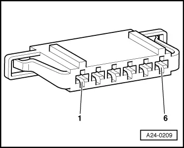
Servicing accelerator linkage - Vehicles with accelerator pedal module 02.99 ä
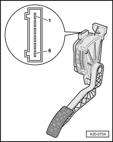
Testing accelerator pedal position sender -G79 - Vehicles with 4-cylinder engine
|
 |
|
|
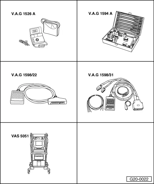
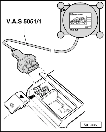
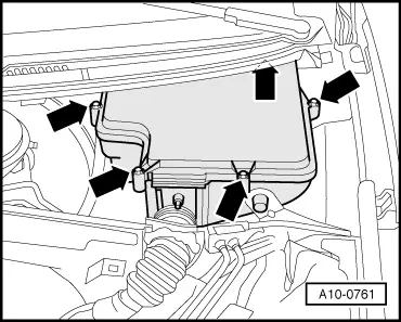
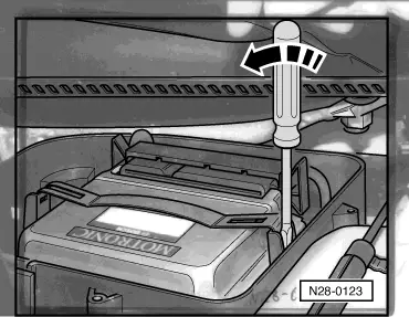
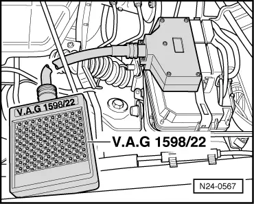
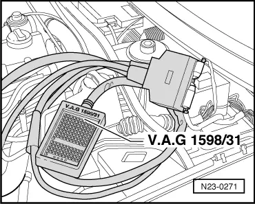
Special tools and workshop equipment required
Test sequence |
 |
|
=> TDI injection and glow plug system (4-cyl. ) 07.97 ä 07.99; Repair group 01; Self-diagnosis => TDI injection and glow plug system (4-cyl.) 08.99 ä; Repair group 01; Self-diagnosis => TDI injection and glow plug system (4-cyl. unit injector); Repair group 01; Self-diagnosis |
| → Indicated on display: |
|
||
|
| → Indicated on display: |
|
||
|
| → Indicated on display: (1...4 = Display zones) |
|
||
Vehicles with manual gearbox
Vehicles with automatic gearbox
All models If the specifications for the initial and/or final readouts are not obtained:
If the display does not change or only changes irregularly: Testing internal resistance
|
 |
||||||||||||||||||||||
1) Only on vehicles with automatic gearbox. If the specifications are not obtained:
|
 |
|
|
Checking wiring connections
|
 |
|
|
 |
|
Warning!
To prevent damage to the electronic components, switch to the respective measuring range before connecting the measuring cable and observe the test prerequisites. Vehicles ä 07.99: |
 |
|
Vehicles 08.99 ä: |
 |
|
All models
|
 |
||||||||||||||||||||||
=> Current flow diagrams, Electrical fault finding and Fitting locations binder |