audi Workshop Repair Guides

Audi Workshop Service and Repair Manuals

Fuel supply system - diesel engines > < Adjusting throttle cable - vehicles with 6-cylinder normally aspirated engine
Fuel supply system - Petrol engines
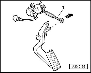
Servicing throttle cable - front-wheel drive and four-wheel drive
Servicing accelerator mechanism - vehicles with 6-cylinder turbo engine
 
N20-0195
  • 6-pin connector
  • 10 Nm
  • Accelerator position sender -G79
    • ◆ Adjusting =>Page 20-134
    • ◆ To remove and install, remove mounting -Item 9 .
  • Cable cam
  • 10 Nm
  • Operating rod
    • ◆ With threaded collar for adjustment =>Page 20-134
 
N20-0195
  • Accelerator pedal stop
    • ◆ Position on vehicles with manual gearbox: marking "H" or "HS" (hand-shift) must be visible
    • ◆ Position on vehicles with automatic gearbox: marking "A" or "AG" must be visible
  • Accelerator pedal
  • Mounting
    • ◆ Removing and installing:

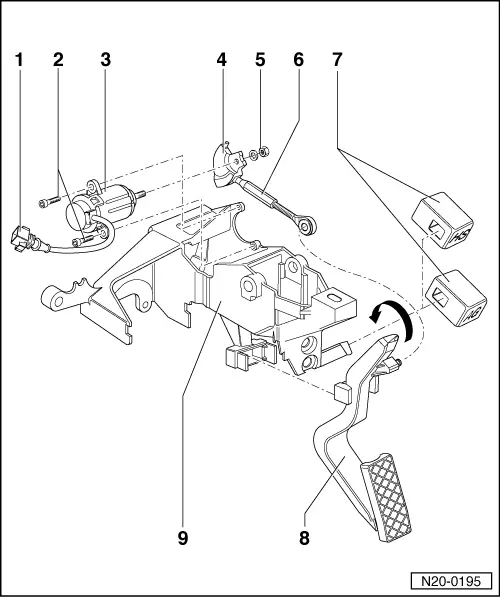
=> Running gear, Front and four-wheel drive; Repair group 46; Removing and installing pedal cluster

Adjusting accelerator position sender

Special tools, testers and auxiliary items

 
A20-0197
  • ◆ Fault reader V.A.G 1551 (or vehicle system tester V.A.G 1552) with cable V.A.G 1551/3

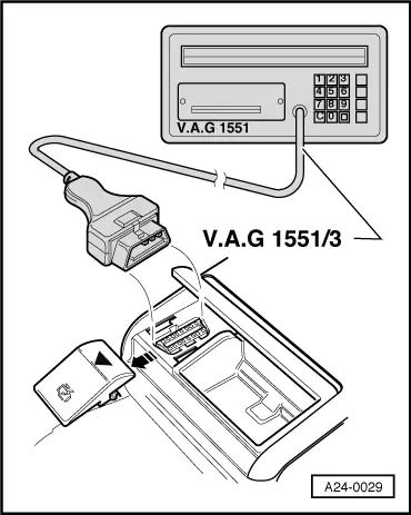
Vehicles with manual gearbox

Requirement for test:

  • ● → Position of accelerator pedal stop: marking"H" or "HS" must be visible.

 
A23-0011

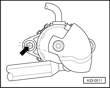
Note:

If accelerator position sender -G79 has been removed:

  • ‒ → Fit cable cam as shown.
  • ◆ In its rest position, the continuation of the spanner flat should intersect with the centre of the drilling -arrow-.
  • ‒ Install sender with cable cam already fitted.
 
A24-0029
  • ‒ → With ignition switched off, connect fault reader V.A.G 1551 or vehicle system tester V.A.G 1552 to diagnostic connector with cable V.A.G 1551/3.

 
→ Indicated in display
V.A.G - SELF DIAGNOSIS    HELP
1 - Rapid data transfer 1)
2 - Flash code output 1)

    1)    appears alternately

  • ‒ Switch on ignition.
  • ‒ Switch on the printer by pressing the PRINT button (indicator lamp in button should light up).
  • ‒ Press key 1 for "Rapid data transfer".
 
→ When this display appears:
Rapid data transfer    HELP
Enter address word XX
  • ‒ Press keys 0 and 1 for address word "Engine electronics" and confirm entry with Q key.
 
→ The display on fault reader V.A.G 1551 will show the control unit identification. For example:
8D0907551 2.7l V6/5VT G    D01     ⇒
Coding 05211    WSC 12345
  • ‒ Press ⇒key.
 
→ When this display appears:
Rapid data transfer    HELP
Select function XX
  • ‒ Press keys 0 and 8 for the function "Read measured value block" and confirm entry with Q key.
 
→ When this display appears:
Read measured value block     Q
Enter display group number XXX
  • ‒ Press keys 0, 6 and 2 for "Display group number 062" and confirm entry with Q key.
 
→ When this display appears:
Read measured value block 62    ⇒
    xx %    xx %    73 %    xx %    
  • ‒ Check display in display zone 3 (accelerator pedal position).
  • ‒ Press accelerator all the way down and hold in position.
    • ‒ Specification: 72 ... 74 % (accelerator pedal pressed down)

If the specification is not attained:

 
A20-0198
  • ‒ → Disengage eyelet of operating rod -1- from accelerator pedal -arrow-.
  • ‒ Turn threaded collar on operating rod.
  • ‒ After completing adjustment, carefully engage operating rod on accelerator pedal.

  • ‒ Check adjustment again:
  • ‒ Press accelerator pedal down slowly.
 
→ Specification: figure in display zone 3 should constantly increase, reaching 72 ... 74 % when the accelerator pedal is pressed down fully.
Read measured value block 62    ⇒
    xx %    xx %    73 %    xx %

Fuel supply system - diesel engines > < Adjusting throttle cable - vehicles with 6-cylinder normally aspirated engine