audi Workshop Repair Guides

Audi Workshop Service and Repair Manuals

Dismantling and assembling fuel manifold with injectors > < Checking system pressure, fuel pressure regulator and holding pressure
Motronic Fuel Injection and Ignition System (4-cyl) Turbo
Servicing Motronic injection system
Checking injectors
 
G24-0022

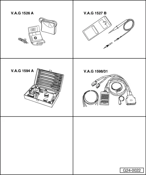
Special tools and workshop equipment required

  • ◆ V.A.G 1526 A
  • ◆ V.A.G 1527 B
  • ◆ V.A.G 1594 A
  • ◆ V.A.G 1598/31

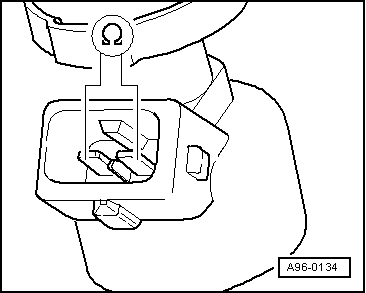
Checking internal resistance

 
A10-0661
  • ‒ → Remove engine cover -arrows-.

  • ‒ Remove connector from the injector which is to be tested.
 
A96-0134
  • ‒ → Connect multimeter to injector to measure resistance.
    • ‒ Specified value: 12...13 ω(at room temperature)

If specified value is not attained:

  • ‒ Renew injector.

If specified value is attained:

  • ‒ Check the power supply.

Checking power supply

Test requirements:

  • ● Fuse for injectors OK.

=> Current Flow Diagrams, Electrical Fault-Finding and Fitting Locations

  • ● Fuel pump relay OK; checking .
  • ‒ Unplug connector on injector to be checked.
 
V96-0749
  • ‒ → Connect voltage tester V.A.G 1527 B as follows:

Connector
contact

Measure to

1

Engine earth

  • ‒ Switch the ignition on.
    • ‒ The LED should light up.

If the LED does not light up:

  • ‒ Check wiring connection between contact 1 and fuse for injector for open circuit:

=> Current Flow Diagrams, Electrical Fault-Finding and Fitting Locations

  • ‒ Rectify open circuit, if necessary

If the LED lights up:

  • ‒ Check injector actuation

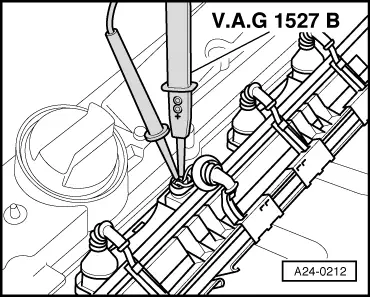
Checking actuation

Test requirements:

  • ● Internal resistance of the valve OK
  • ‒ Push back rubber grommet of plug of injector but leave plug attached.
 
A24-0212
  • ‒ → Connect up voltage tester V.A.G 1527 B between receptacles 2 (signal) and 1 (positive).
  • ‒ Operate the starter briefly (the engine may start).
    • ‒ The LED should flash.

Note:

Voltage testers with a low current draw continue to glow faintly between actuation from the engine control unit (rather than extinguishing completely) and become slightly brighter when actuated.

If LED does not flash:

  • ‒ Connect the V.A.G 1598/31 test box to wiring harness leading to engine control unit; the engine control unit should not be connected .
 
V96-0749
  • ‒ → Check for open circuit and short to positive or earth in the following wiring connections:

Cylinder

Injector connector
contact

Test box V.A.G 1598/31

1

2

96

2

2

89

3

2

97

4

2

88

  • ‒ Rectify any open/short circuit as necessary.

If the wiring is OK:

  • ‒ Fit a new engine control unit => Page 24-23.

Dismantling and assembling fuel manifold with injectors > < Checking system pressure, fuel pressure regulator and holding pressure