audi Workshop Repair Guides

Audi Workshop Service and Repair Manuals

Dismantling and assembling air cleaner > < Technical data
Motronic Fuel Injection and Ignition System (4-cyl) Turbo
Servicing Motronic injection system
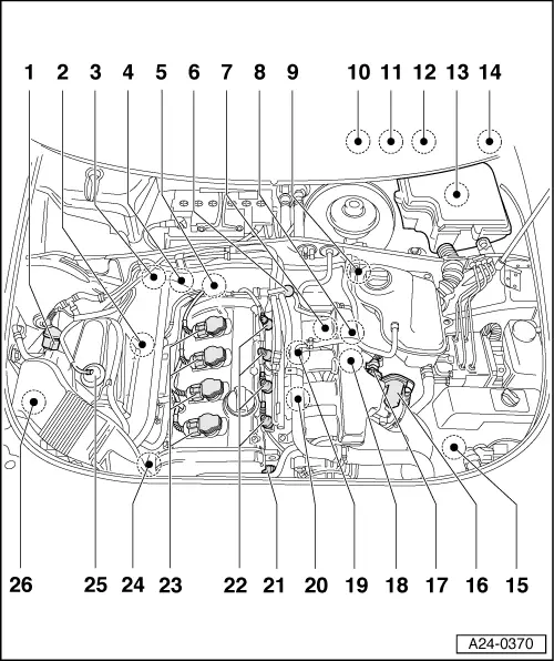
Fitting locations overview
 
A24-0370
  • Solenoid valve 1 for activated charcoal filter -N80
    • ◆ Checking
  • Lambda probe upstream of catalytic converter -G39 - 55Nm
    • ◆ Constant lambda probe
    • ◆ Check lambda probe and lambda control upstream of catalytic converter
    • ◆ Check lambda probe ageing upstream of catalytic converter=> Page 24-86
    • ◆ Check lambda probe heating upstream of catalytic converter => Page 24-90
    • ◆ Removing and installing
 
A24-0370
  • Check lambda probe downstream of catalytic converter -G130 - 55Nm
    • ◆ Check lambda probe and lambda control downstream of catalytic converter => Page 24-95
    • ◆ Check lambda probe heating downstream of catalytic converter => Page 24-107
    • ◆ Removing and installing
  • Combi valve for secondary air inlet
    • ◆ Checking, removing and installing:

=> 4-cylinder engine (5-valve turbo), Mechanical components; Repair group 26; Check secondary air system

  • Coolant temperature sender -G62
    • ◆ Checking
 
A24-0370
  • Fuel pressure regulator
    • ◆ Checking => Page 24-35
  • Engine speed sender -G28
    • ◆ Checking => Page 28-26
  • Checking secondary air inlet valve
    -N112
    • ◆ Fitting location =>Fig.24-14
    • ◆ Checking:

=> 4-cylinder engine (5-valve turbo), Mechanical components; Repair group 26; Check secondary air system

    • ◆ Connector green
  • Bracket for connectors
    • ◆ Fitting location => Fig.24-13
    • ◆ Accessible with coolant expansion tank removed and moved to side
 
A24-0370
  • Instrument cluster:
    • ◆ With fault lamp for electronic throttle -K132 ("EPC" warning lamp). Notes on EPC warning lamp .
    • ◆ With exhaust warning lamp -K83. Notes on exhaust warning lamp
  • Gas pedal position sender -G79 and sender 2 for gas pedal position -G185
    • ◆ Fitting location => Fig.24-15
    • ◆ Checking
    • ◆ Adapt kickdown function
  • Brake light switch - F and brake pedal switch -F47
    • ◆ Fitting location => Fig.24-14
 
A24-0370
  • Electronics box in plenum chamber
    • ◆ Fitting locations =>Fig.24-15
    • ◆ Fitting location for engine control unit -J220 with integrated altitude sender -F96
    • ◆ Check power supply to engine control unit => Page 28-35.
    • ◆ Procedure following interruption of voltage supply => Page 24-22
    • ◆ Replace engine control unit => Page 24-23
    • ◆ Fitting location for secondary air pump relay -J299
    • ◆ Check secondary air pump relay -J299:

=> 4-cylinder engine (5-valve turbo), Mechanical components; Repair group 26; Check secondary air system

 
A24-0370
    • ◆ Fitting location for power supply relay for Motronic -J271
    • ◆ Check power supply relay for Motronic -J271
    • ◆ Fitting location for fuse S130 for secondary air pump
  • Clutch pedal switch -F36
    • ◆ Fitting location => Fig.24-14
  • Boost pressure sender -G31
    • ◆ Fitting location =>Fig.24-16
    • ◆ Checking:

=> 4-cylinder Engine (5-valve Turbo), Mechanical components; Repair group 21; Checking charge air system with exhaust gas turbocharger

 
A24-0370
  • Throttle valve control unit -J338
    • ◆ With throttle valve drive -G186, angle sender for throttle valve drive -G187 and angle sender 2 for throttle valve drive -G188
    • ◆ Checking => Page 24-124
  • Intake air temperature sender -G42
    • ◆ Checking
  • Air recirculation valve for turbocharger -N249
    • ◆ Fitting location =>Fig.24-14
    • ◆ Connector blue
  • Knock sensor 1 -G61
  • Knock sensor 2 -G66
  • Hall sender -G40
    • ◆ Checking => Page 28-46
 
A24-0370
  • Injector -N30...-N33
    • ◆ Checking => Page 24-40
    • ◆ Removing and installing
  • Ignition coils -N, -N128, -N158, -N163
    • ◆ Checking
  • Boost pressure control solenoid valve -N75
    • ◆ Checking:

=> 4-cylinder Engine (5-valve Turbo), Mechanical components; Repair group 21; Checking charge air system with exhaust gas turbocharger

  • Air mass meter -G70
    • ◆ Checking
  • Secondary air pump motor -V101
    • ◆ Checking:

=> 4-cylinder engine (5-valve turbo), Mechanical components; Repair group 26; Check secondary air system

 
A24-0392

→ Fig.1    Fitting location for connectors

The following connections are located underneath the coolant expansion tank:

  •     1 -    4-pin connector, brown
    • for lambda probe downstream of catalytic converter -G130 and heater for lambda probe -Z29 (bank 1, probe 2)
  •     2 -    6-pin connector, black
    • for lambda probe downstream of catalytic converter -G39 and heater for lambda probe -Z19 (bank 1, probe 1)
  •     3 -    3-pin connector, grey
    • for engine speed sender -G28
  •     4 -    3-pin connector, blue
    • For knock sensor 2 -G66
  •     5 -    3-pin connector, green
    • for knock sensor 1 -G61
 
A97-0110

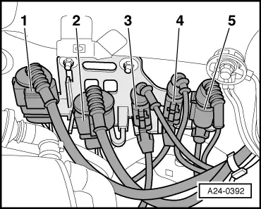
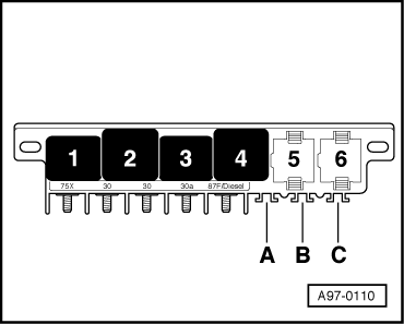
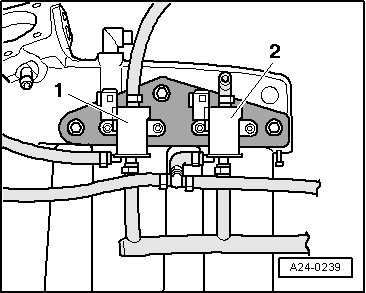
→ Fig.2    Fitting location for secondary air inlet valve -J17

Fuel pump relay -J17 on central electrics in driver's left footwell, position 4.

 
A24-0243

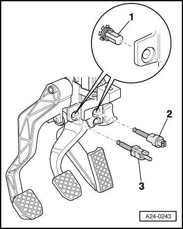
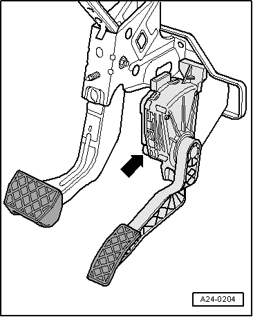
→ Fig.3    Fitting location for brake light switch -F and brake pedal switch -F47, clutch pedal switch -F36

  •     1 -    Clip
  •     2 -     Clutch pedal switch -F36
  •     3 -    Brake light switch -F, brake pedal switch -F47

Note:

Switch must only be installed once in order to ensure that it is sufficiently tight.

Adjust switch:

=> Brake systems; Repair group 46; Removing and installing brake pedal

 
A24-0239

→ Fig.4    Installation position secondary air inlet valve

-N112 and air recirculation valve for turbocharger

-N249

  • ◆ Location: underneath intake pipe
  •     1 -    Air recirculation for turbocharger -N249
  •     2 -    Secondary air inlet valve -N112

Note:

The illustration shows bottom view of intake pipe.

 
A24-0204

→ Fig.5    Installation position for accelerator pedal position sender -G79 and sender 2 for accelerator pedal position -G185

 
A26-0357

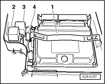
→ Fig.6    Fitting locations in electronics box (plenum chamber)

  •     1 -    Engine control unit
  •     2 -    Secondary air pump relay -J299
  •     3 -    Power supply relay for Motronic -J271
  •     4 -    Fuse S130 for secondary air pump
 
A21-0167

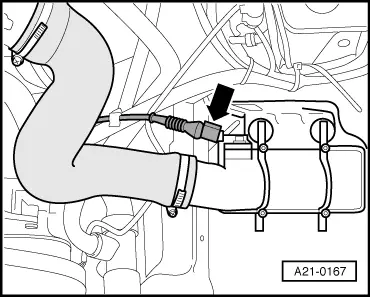
→ Fig.7    Fitting location boost pressure sender -G31

Boost pressure sender -G31 -arrow- screwed into top of charge air cooler.

Dismantling and assembling air cleaner > < Technical data