audi Workshop Repair Guides

Audi Workshop Service and Repair Manuals

Checking air mass meter -G70 > < Testing injection quantity, leak tightness and spray pattern of injectors
Motronic Fuel Injection and Ignition System (4-cyl) Turbo
Servicing Motronic injection system
Fuel pump relay -J17 and actuation
 
G24-0021

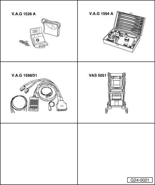
Special tools and workshop equipment required

  • ◆ V.A.G 1526 A
  • ◆ V.A.G 1594 A
  • ◆ V.A.G 1598/31
  • ◆ VAS 5051 with VAS 5051/1
  • or
  • ◆ V.A.G 1551 with V.A.G 1551/3 A

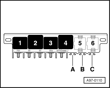
Fitting location => Fitting location overview Page 24-5

The fuel pump and certain components of the injection system are supplied with power by way of the fuel pump relay -J17.

The fuel pump relay -J17 is only energised when the engine is running, i.e. the relay is only connected to earth (via the engine control unit) when engine speed pulses are detected in the engine control unit.

Test requirements:

  • ● Battery voltage at least 12.7 V

Functional check of fuel pump relay

  • ‒ Remove driver's storage compartment.
  • ‒ Connect vehicle diagnostic, testing and information system VAS 5051 or fault reader V.A.G 1551 and select engine electronics control unit with "Address word" 01
    For this purpose, the ignition must be switched on.
  • ‒ Initiate final control diagnosis and actuate ACF solenoid valve -N80.
 
A97-0110
    • ‒ → Fuel pump relay (in the central electric's, electronics box, passenger's footwell, position 4) should pull and fuel pump should run.

A - If relay does not respond:

  • ‒ Check voltage supply of fuel pump relay => Page 24-57.
  • ‒ Check actuation of fuel pump relay.

B - If relay is energised but fuel pump does not run:

  • ‒ Check voltage supply for fuel pump and components (via fuel pump relay) .
 
A24-0100

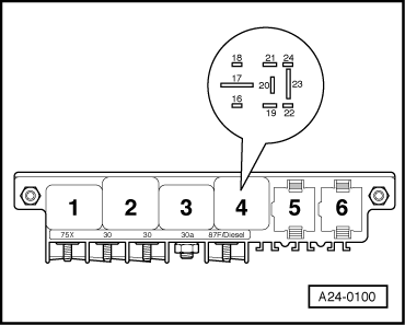
Checking voltage supply of fuel pump relay

  • ‒ Disconnect fuel pump relay.
  • ‒ → Connect the multimeter to contact 17 of relay socket and earth to measure voltage.
    • ‒ Specified value: approx. battery voltage

If specified value is not attained:

  • ‒ Replace central electric's.

Checking actuation of fuel pump relay

  • ‒ Switch ignition off.
  • ‒ Connect the V.A.G 1598/31 test box to wiring harness leading to engine control unit; the engine control unit should not be connected => Page 24-19.
  • ‒ Switch the ignition on.
  • ‒ Jumper contacts 1 and 65 at test box with leads from adapter set V.A.G 1594A.
 
A97-0110
    • ‒ → Fuel pump relay (on central electrics in passenger's footwell, position 4) must be energised.

If the relay pulls now, but not during final control diagnosis:

  • ‒ Fit a new engine control unit => Page 24-23.

If the relay does not pick up:

  • ‒ Switch ignition off.
  • ‒ Disconnect cable link.
  • ‒ Disconnect fuel pump relay.
 
A24-0100
  • ‒ → Connect multimeter as follows to measure voltage.

Central electrics
In driver's footwell on left, position 4
contact

Measure to

19

Engine earth

  • ‒ Switch the ignition on.
    • ‒ Specified value: approx. battery voltage

If specified value is not attained:

  • ‒ Check the wiring connections.

=> Current Flow Diagrams, Electrical Fault-Finding and Fitting Locations

If specified value is attained:

  • ‒ Check for open circuit and short to positive or earth in the following wiring connections:

Central electrics
In driver's footwell on left, position 4
contact

Test box V.A.G 1598/31


Socket

16

65

  • ‒ Rectify any open/short circuit as necessary.

If no fault is found:

  • ‒ Replace the fuel pump relay -J17.
  • ‒ Reconnect engine control unit.

Checking voltage supply of fuel pump and components

 
A97-0119
  • ‒ → Disconnect fuses S228, S229 and S234 (positions 28, 32 and 34) in fuse holder.
  • ‒ Initiate final control diagnosis and actuate ACF solenoid valve -N80.
  • ‒ To measure the voltage, connect multimeter to earth and to one of the contacts of the following fuses in the fuse holder.

Securing clip

Specified value at one of the contacts

S228

approx. battery voltage

S232

approx. battery voltage

S234

approx. battery voltage

If specified values are not attained:

  • ‒ Repeat the test at the other contact of the fuse base.

If the specifications are still not attained:

  • ‒ Check the wiring connections.

=> Current Flow Diagrams, Electrical Fault-Finding and Fitting Locations

If no fault is found:

  • ‒ Replace the fuel pump relay -J17.
  • ‒ Reinsert the fuses.

Checking air mass meter -G70 > < Testing injection quantity, leak tightness and spray pattern of injectors