audi Workshop Repair Guides

Audi Workshop Service and Repair Manuals

Testing the boost pressure system > < Testing injectors
Motronic fuel injection and ignition system (4-cyl.turbo) > 07.96
Repairing the Motronic fuel injection system
Testing fuel pump relay

Voltage is supplied to the fuel pump and some injection system components via the fuel pump relay (J17).

The condition for the closing of the fuel pump relay (J17) is that the engine should be turning. This means that the relay only acquires an earth (via the engine control unit) when a revolution pulse is recognised in the engine control unit.

Test conditions

  • ● Battery voltage OK.

Functional testing of fuel pump relay

  • ‒ Start actuator diagnosis and activate an injector .
 
V97-6548
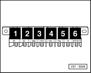
  • → The fuel pump relay (central electrics, relay position 6) must pick up...
  • ‒ If the relay does not pick up, test activation of fuel pump relay
  • ...and the fuel pump must run.
  • ‒ If the fuel pump does not run, check activation for fuel pump and components

Check activation of fuel pump relay

  • ‒ Switch off ignition.
 
V97-6548
  • ‒ Connect the V.A.G 1598/22 test box to the wiring harness for the engine control unit
    => Page 24-6.
  • ‒ Connect together sockets 4 and 2 on the test box using an auxiliary cable from V.A.G 1594.
  • ‒ Switch the ignition on.
  • → Specified result: The fuel pump relay (central electrics, relay position 6) must pick up.

If the relay picks up but not during the actuator diagnosis:

  • ‒ Renew engine control unit
 
A24-0081

If the relay does not pick up:

  • ‒ Switch off ignition.
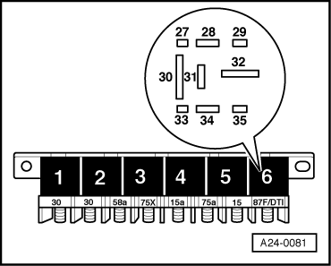
  • ‒ → Remove fuel pump relay from relay base (central electrics, relay position 6).
  • ‒ Connect the multimeter for voltage measurement to contact 2 on the relay base and to earth.
  • ‒ Switch the ignition on.
  • Specified result: approx. battery voltage

If specified result is not attained:

  • ‒ Check the wiring connections.

=> Circuit diagrams, Electrical Fault Finding and Installation Location binder

If the specified result is attained:

  • ‒ Switch off ignition.

The following wiring connections should be checked for open circuits and/or short to positive or negative.

 
A24-0081

Central electrics, relay base 6, contact

Test box V.A.G 1598/22, socket.

29

4

  • ‒ If necessary, rectify open circuit or short circuit.

If no fault is detected in the line:

  • ‒ Renew the fuel pump relay (J17).

Check activation of fuel pump and components

 
A97-0022
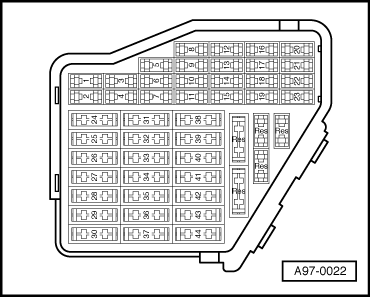
  • ‒ → Withdraw the fuses 28, 29 and 34.
  • ‒ Start actuator diagnosis and activate an injector => Page 01-37.
  • ‒ Connect the multimeter for voltage measurement to the left-hand and right-hand contacts of the following fuses:

Fuse No.

Specified result at left-hand or right-hand contact

28

ca. Battery voltage

29

approx. battery voltage

34

approx. battery voltage

If specified result is not attained:

  • ‒ Check the wiring connections.

=> Circuit diagrams, Electrical Fault Finding and Installation Location binder

If no fault is detected in the line:

  • ‒ Renew the fuel pump relay (J17).

Testing the boost pressure system > < Testing injectors