audi Workshop Repair Guides

Audi Workshop Service and Repair Manuals

Testing auxiliary signals > < Checking the intake air temperature sensor
Motronic fuel injection and ignition system (4-cyl.turbo) > 07.96
Testing control unit input values
Testing airflow meter
  • ‒ Read measured value block, Display Group 02, engine at idling speed
 
→ Indicated on display:
Read measured value block 2    ⇒
    1    2    3    4
  • ‒ Check readout in display zone 4.
  • Specified result: 1.8...4.0 g/s

If specified result is not attained:

  • ‒ Switch off ignition.
  • ‒ Detach the connector for the airflow meter =>Overview of installation locations, Page 24-4.
  • ‒ Switch the ignition on.
 
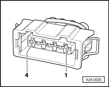
A24-0020
  • ‒ → Connect the multimeter for voltage measurement to the following contacts on the connector:

4-pin connector on the wiring harness, contact.

Specified result

3 + earth

Battery voltage

3 + 1

Battery voltage

3 + 2

Battery voltage

If the specified results are not obtained:

  • ‒ Connect the V.A.G 1598/22 test box to the wiring harness for the engine control unit.
    .

The following wiring connections should be checked for open circuits and/or short to positive or negative:

 
A24-0020

4-pin connector on the wiring harness, contact.

Test box V.A.G 1598/22, socket.

1

2

2

12

3

to fuse

4

13

  • ‒ Rectify short circuit or open circuit if necessary.

If no fault is detected in the wiring:

  • ‒ Renew airflow meter (G70).

Testing auxiliary signals > < Checking the intake air temperature sensor