audi Workshop Repair Guides

Audi Workshop Service and Repair Manuals

Test coolant temperature sensor > < Checking the intake air temperature sender
Motronic Fuel Injection and Ignition System (6-cyl. Turbo)
Checking ignition system
Testing engine speed sender

Note:

  • ◆ The engine speed sender is a combined speed sender and reference mark sender. The engine cannot be started without a signal from the G28 engine speed sender. If the signal from the -G28 engine speed sender fails while the engine is running, the engine will cut out immediately.

Testing engine speed sender

Fitting location of sender and connector
.

  • ‒ Before carrying out the test, make sure that the sender is correctly installed and firmly seated.
  • ‒ Disconnect connector for engine speed sender (identification: grey connector).
 
A24-0089
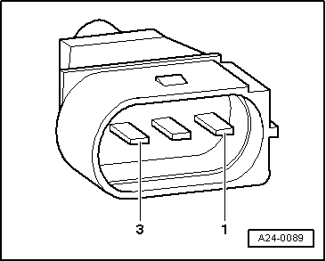
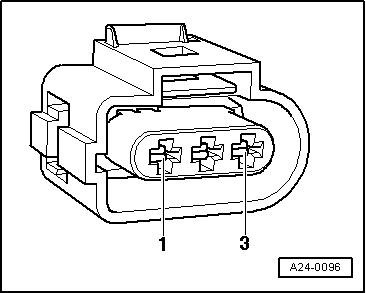
  • ‒ → Connect hand-held multimeter V.A.G 1526 (resistance test range) to contacts 2 and 3 on connector for engine speed sender using test lead from V.A.G 1594.

Specification: 730...1000 ω.

Note:

The resistance figure for the engine speed sender is associated with a temperature of 20 °C.

The resistance increases with increasing temperature.

  • ‒ If the value does not match specification, fit a new engine speed sender.
  • ‒ If specification is attained, connect hand-held multimeter (resistance range) to contacts 2 and 1 (earth) and to contacts 3 and 1 (earth).

Specification: infinite resistance (open circuit) in each test.

  • ‒ If specified result is not achieved, renew engine speed sensor.
  • ‒ If the value does match specification, test the wiring between the sender connector and the engine control unit as follows:
 
A24-0096
  • ‒ Connect test box V.A.G 1598/31 to wiring harness for engine control unit; do not connect the engine control unit => Page 24-23.
  • ‒ → Test continuity of screening from contact 1 on sender connector to socket 108 on test box.

Specification: max. 1 ω.

  • ‒ Check continuity of negative line from contact 2 on sender connector to socket 90 on test box.

Specification: max. 1 ω.

  • ‒ Test continuity of signal wire from contact 3 on sender connector to socket 82 on test box.

Specification: max. 1 ω.

  • ‒ If specified result is not achieved, rectify short or open circuit in wiring between sensor connector and control unit connector.

Contact on sender connector

Contact on control unit connector

1
2
3

108
90
82

  • ‒ If no open circuits or short circuits are found, fit a new engine control unit .

Test coolant temperature sensor > < Checking the intake air temperature sender