
A4 Mk1
| → Indicated on display: |
|
||
|
| → Indicated on display: |
|
||
|
| → When adjacent display appears: |
|
||
|
| → Example: |
|
||
|
Note: Display group 125 indicates the systems which communicate with the engine control unit via the CAN data bus. (The ABS and instrument cluster control unit in the example). If these systems are not installed, the respective display zones in display group 125 remain blank. "Gearbox 1" would be indicated in display zone 1 and "Air conditioner 1" in display zone 4 if these systems communicate with the engine control unit via "CAN". |
| → Check in the same way with display group number 126. |
|
||
|
Note: Display group 126 indicates the systems which communicate with the engine control unit via the CAN data bus. If these systems are not installed, the respective display zones remain blank. The following systems are displayed in display group 126, however only if they are available: Display zone 1:Automatic distance control; display: "Distance 1". Display zone 2:Steering angle sensor; display: "Steering angle 1" Display zone 3:Airbag; display: "Airbag 1". Display zone 4:Vehicle's electrical system; display: "el. CE 1".
|
| → Indicated on display: |
|
||
If a control unit answers with its identification, the number of faults stored or "No fault detected" appears on the display. Any system faults stored will be displayed in sequence and printed out. The V.A.G 1551 will then transmit the next address word. |
 |
|||||||||
|
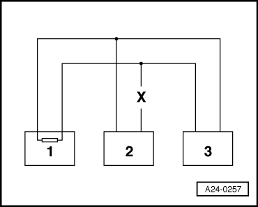
Example 1: With the faults stored in the fault memories it can be seen that the control unit 1 does not communicate with control units 2 and 3.
=> Current Flow Diagrams, Electrical Fault-Finding and Fitting Locations
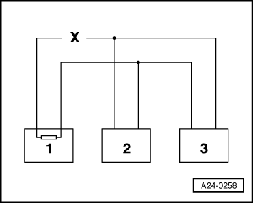
Example 2: |
 |
|||||||||
|
With the faults stored in the fault memories it can be seen that the control unit 2 does not communicate with control units 1 and 3.
=> Current Flow Diagrams, Electrical Fault-Finding and Fitting Locations
Example 3: With the faults stored in the fault memories it can be seen that there is no sending or receiving operation possible in any of the control units. |
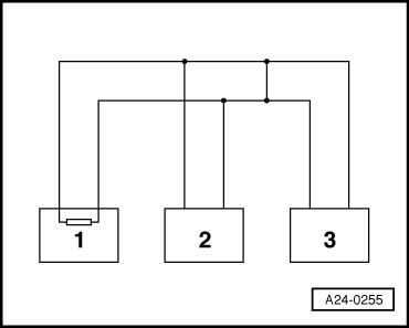 |
|||||||||
=> Current Flow Diagrams, Electrical Fault-Finding and Fitting Locations |
 |
|
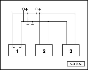
If cause of fault "Data bus drive defective" cannot be found in bus lines check whether one of the control units is responsible for the fault. All the control units that communicate via the CAN data bus are still disconnected. The ignition is switched off.
|