
A4 Mk1
|
Checking ignition system
Checking coolant temperature sender -G62
|
 |
|
|
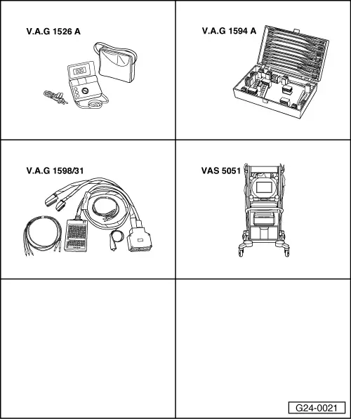
Special tools and workshop equipment required
Fitting location => Fitting location overview Page 24-5 Test requirements:
Test sequence
|
| → When adjacent display appears: |
|
||
|
| → When adjacent display appears: |
|
||
|
| → Indicated on display: |
|
|||||||||||||||||||||||||||||||||||
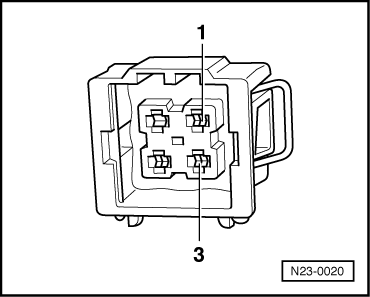
If display zone 3 shows an implausible value: Note: To gain access to the coolant temperature sender the intake hose between air mass meter and air intake elbow must be removed.
Coolant temperature sender with square plug: | ||||||||||||||||||||||||||||||||||||
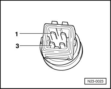 |
|
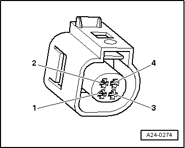
Coolant temperature sender with oval plug: |
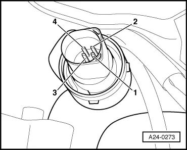 |
|
All models: Range A shows resistance values for temperature range 0...50 °C and range B the values for temperature range 50...100 °C. |
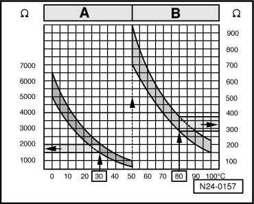 |
|
|
→ Sample readings:
If specified value is not attained:
If specified value is attained:
Coolant temperature sender with square plug: |
 |
|||||||
Coolant temperature sender with oval plug: |
 |
||||||
All models:
If no wiring fault is detected:
|